
What Is a BMS Wire Harness? Cell Voltage, Temperature Sensing & Balancing Explained
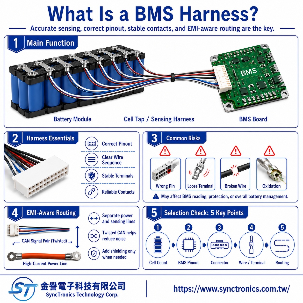
A BMS wire harness connects the battery module to the Battery Management System (BMS) and carries cell-voltage, temperature, and other monitoring signals.
Unlike a high-current power harness, a BMS harness is primarily designed for accurate sensing, correct wire sequence, stable electrical contact, and noise control. Incorrect pin assignments, loose terminals, or broken sensing wires can directly affect how the BMS interprets battery conditions.
What Signals Are Commonly Included in a BMS Wire Harness?
The exact configuration depends on the battery module and BMS architecture, but common circuits include:
|
Circuit |
Main Function |
|
Cell-voltage wires |
Measure the electrical potential of individual series-connected cells |
|
Temperature-sensing wires |
Connect NTC thermistors or other temperature sensors |
|
Balancing-related circuits |
Support cell-balancing functions depending on BMS architecture |
|
Communication / control wires |
Carry CAN or other control signals where required |
The total pin count typically increases with the number of series cells, temperature-sensing points, and additional system functions.
Why Are Cell-Voltage Sensing Wires Important?
The BMS needs to monitor individual cell voltages to evaluate battery condition and manage charging, discharging, and protection functions.
These circuits normally carry relatively low current, but they require reliable electrical connections.
Important considerations include:
- Correct pin assignment
- Correct cell sequence
- Stable terminal contact
- No open circuits
- No terminal back-out or corrosion
- Matching pin definitions between the BMS and battery module
Two BMS harnesses should therefore not be considered interchangeable simply because they use connectors with the same number of pins.
The complete pinout and wiring diagram must be verified.
Is a Balancing Wire a Separate Signal Wire?
Not always.
In many BMS designs using passive cell balancing, the same cell-sense wiring used for voltage measurement may also form part of the balancing current path.
This is why some products are commonly referred to as a balance harness or balancing harness.
A more accurate engineering interpretation is:
Cell-sense wires primarily monitor cell voltage and may also participate in balancing depending on the BMS circuit design.
Whether separate balancing conductors are required should be confirmed from the actual BMS architecture and product documentation.
What Do Temperature-Sensing Wires Monitor?
Battery modules often use NTC thermistors or other temperature sensors to monitor cells, modules, busbars, or other selected locations.
The BMS receives these temperature signals through the harness.
Problems such as an open circuit, poor contact, or incorrect pin assignment can result in:
- Abnormal temperature readings
- Sensor detection errors
- BMS fault conditions
- Reduced effectiveness of protection functions
The sensor type, circuit design, and pin assignment must therefore match the BMS design rather than simply connecting additional wires.
Does a BMS Harness Need EMI Protection?
It may, especially when routed close to high-current cables, inverters, motors, or switching power electronics.
Depending on the signal type, useful design measures may include:
|
Design Consideration |
Main Purpose |
|
Separation from high-current wiring |
Reduces coupling from switching noise |
|
Twisted-pair communication lines |
Improves noise immunity for differential signals |
|
Shielding where required |
Helps reduce EMI in more demanding environments |
|
Controlled routing |
Avoids long parallel runs with noisy power conductors |
Not every BMS sensing wire requires shielding or twisted-pair construction.
The correct approach depends on the signal type and overall EMC design.
What Should Be Checked When Selecting a BMS Wire Harness?
For a BMS harness, the key requirement is not simply using a larger conductor. The electrical definition and assembly must be correct.
|
Evaluation Area |
What to Confirm |
|
Pinout |
Cell order, polarity, temperature, communication assignments |
|
Connector |
Pin count, keying, terminal retention, mating part |
|
Wire |
Conductor size, insulation, temperature and voltage rating |
|
Terminal |
Applicable wire range, crimp requirements, contact reliability |
|
Routing |
Separation from high-current and high-noise circuits |
|
Assembly |
Wire sequence, labeling, fixation, strain relief |
Incorrect cell sequencing can do more than produce an invalid reading. It may apply an unintended electrical potential to the BMS sensing inputs.
For this reason, wiring diagrams and pin definitions are critical.
Summary
A BMS wire harness provides the monitoring and control connection between the battery module and the Battery Management System.
Its main functions may include cell-voltage sensing, temperature monitoring, balancing-related circuits, and communication or control signals.
Unlike a high-current power harness, its design priorities are correct pinout, stable terminal contact, accurate sensing, clear wire sequence, and appropriate noise control.
A practical design sequence is:
Battery Configuration → BMS Pinout → Connector → Terminal → Wire → Routing
Final wiring definitions and electrical requirements should always be confirmed against the BMS documentation, battery-module drawings, and project-specific specifications.
SyncTronics Solutions
SyncTronics Technology can support energy storage systems, battery modules, and BMS applications by assisting with BMS wire harness pin configuration, wire selection, terminals, connectors, and wiring sequence, including cell-voltage sensing, temperature monitoring, and communication circuits.
For NPI, OEM/ODM, and customized battery harness projects, SyncTronics can also support specification review based on BMS drawings, connectors, terminals, wires, and actual module configurations, together with alternative part evaluation and supply chain integration. Final pinout and electrical requirements should be confirmed against BMS manufacturer documentation and project drawings.
Need Wire Harnesses, Connectors, Electromechanical Components, or Custom Solutions? Contact Us Today
Whether you are looking for connectors, cables, wire harness assemblies, electromechanical components, or complete electronic interconnect solutions, SyncTronics provides professional technical support and engineering evaluation for product selection, specification verification, New Product Introduction (NPI), OEM/ODM customization, as well as high-speed transmission, high-reliability, and other specialized application requirements.
We welcome you to visit our Contact Us page and share your project requirements and contact information. Our team is committed to responding quickly and professionally, evaluating the most suitable products and electronic interconnect solutions based on your product specifications, application requirements, and project objectives. We also provide technical recommendations and customized engineering support to help shorten product selection and development time, reduce project risks, and accelerate your path to mass production. We look forward to the opportunity to work with you and provide reliable technical support and practical solutions for every stage of your project.
Related Articles
What Is Connector Pin Count? Complete Guide | SyncTronics Technology
What Is a Twisted Pair Cable? How Does It Reduce EMI? | SyncTronics Technology
What Is a Shielded Cable? Shielding Principles and Applications Explained | SyncTronics Technology
Disclaimer and Technical Exchange Statement
This content is compiled based on publicly available information and industry experience, intended solely for reference during technical exchanges. It does not constitute any commercial, technical, or legal advice or basis.
The specifications, materials, manufacturing processes, application methods, and related information described herein may vary due to differing design conditions, environmental factors, or usage scenarios. No guarantees are made regarding the completeness, correctness, or suitability of such content.
Readers should verify the suitability with the responsible design or technical personnel based on actual application scenarios, and independently assess all associated risks.
Frequently Asked Questions (FAQ)
- What is Connector Knowledge
- Wire Related issues
- What Is Wire Harness Assembly? Complete Guide to the Process, Applications, and Benefits
- 60W vs. 100W vs. 140W vs. 240W USB-C Cables: What's the Difference?
- Are All USB-C Cables the Same?
- Solar vs. Energy Storage Cables: Weather Resistance, Voltage & Selection Guide
- What Is a BMS Wire Harness? Cell Voltage, Temperature Sensing & Balancing Explained
- How to Select Energy Storage Power Wire Harnesses: Current, Voltage, Temperature Rise & Flame Retardancy
- What Is Silicone Wire? High-Temperature Properties, Structure & Selection
- How to Choose AWG Wire Size for Drone Power Cables
- How to Select Drone Wires: Lightweight Design, Flexibility, Heat Resistance and Waterproofing
- What Is a High-Speed Transmission Cable?
- What Is a Twisted Pair Cable? Why Does It Reduce Electromagnetic Interference?
- Industrial Cable Applications Explained: How to Select High Temperature, Waterproof, and High Reliability Cables
- What Are the Steps in Wire Processing? Complete Guide to the Manufacturing Process
- What Are Wire Cutting, Wire Stripping, Crimping, and Assembly?
- What Is a High Temperature Cable?
- What Is an Oil-Resistant and Abrasion-Resistant Cable?
- What Is a Waterproof Cable?
- What Are UL-Rated Wires?
- What Is AWG Wire Gauge? How Do You Choose the Right Wire Size?
- What Is a Controlled Impedance Cable?
- What Is a Differential Signal Cable?
- What Is a High Frequency Cable?
- What Is the Difference Between a Coaxial Cable and a Ribbon Cable?
- Older Network Cable Versions Explained: What Are CAT3, CAT4, and CAT5?
- CAT5e vs CAT6 vs CAT6a vs CAT7 vs CAT8 Complete Guide
- STP vs UTP Ethernet Cables: Understanding Shielded and Unshielded Twisted Pair Differences
- What Are the Differences Between USB, HDMI, D-Sub, and LVDS Cables?
- Materials-Related
- Regulatory Issues
- Electronic issues
- Manufacturing Technology
- Testing & Verification
- Quality Management
- History & Evolution