
Drone Wire EMI: Power, Signal & Shielding
Drone wiring can be affected by EMI (Electromagnetic Interference) because motors, ESCs, high-current power cables, DC/DC converters, flight controllers, sensors, and communication interfaces are often installed within a very compact space. Rapidly changing currents and switching signals can couple unwanted noise into nearby wiring through electric fields, magnetic fields, or conducted paths, potentially causing sensor errors, unstable communication, or unreliable system behavior.
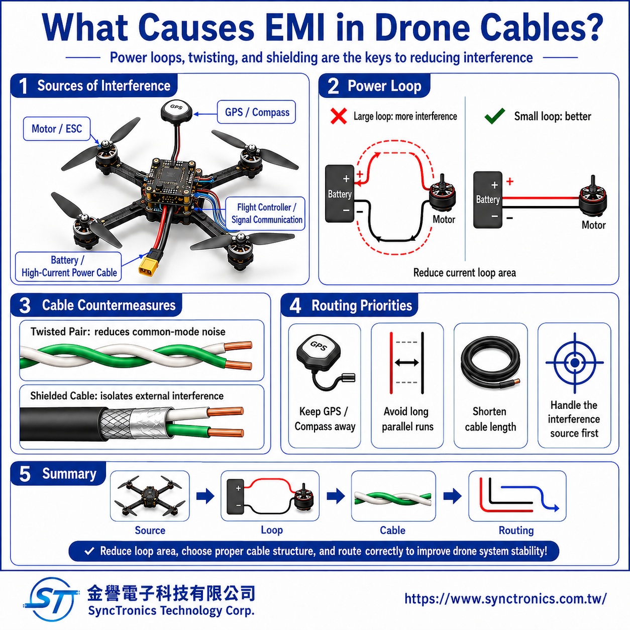
The most effective approach is not to rely on shielding alone. EMI should be controlled through a combination of power-loop design, physical separation, twisted-pair wiring, shielding, grounding, and proper cable routing.
What Are the Main EMI Sources Inside a Drone?
Several components can become significant sources of electromagnetic noise.
Motors and ESCs
Electronic Speed Controllers (ESCs) rapidly switch current to control motor speed. These high-current switching waveforms can generate substantial electrical and magnetic noise around the ESC and motor phase wiring.
Battery and High-Current Power Wiring
Battery cables, power distribution wiring, and ESC power leads carry relatively high current. When current changes quickly, the surrounding magnetic field changes as well.
The physical relationship between the positive and return conductors is therefore important.
DC/DC Converters and Switching Power Supplies
BECs, voltage regulators, and other switching power supplies operate at switching frequencies that may introduce conducted or radiated noise into nearby circuits.
Digital and Wireless Electronics
High-speed digital circuits can also generate electromagnetic emissions, while GPS receivers, sensors, and communication interfaces may act as sensitive receiving paths.
For drones in particular, the magnetometer or compass should be kept away from motors, ESCs, and high-current power wiring whenever possible, because magnetic fields generated by these components can interfere with heading measurements.
Why Can Power Cables Interfere with Signal Wires?
Any conductor carrying current produces a magnetic field.
If the positive and return conductors of a drone power circuit are routed far apart, the current-loop area becomes larger. A larger loop generally makes magnetic-field coupling more difficult to control.
One important design principle is therefore:
Keep the supply and return conductors close together to minimize current-loop area.
Battery positive and negative leads, for example, should not be routed far apart simply for installation convenience while sensitive signal wiring passes between them.
High-current power cables should also avoid long parallel runs next to GPS, compass, sensor, or low-level signal wiring whenever practical.
Which Drone Signals Are Most Sensitive to EMI?
Different interfaces have different susceptibility characteristics.
|
Circuit Type |
EMI Consideration |
Common Design Approach |
|
High-current power wiring |
Can generate strong magnetic fields and switching noise |
Keep supply and return close together, minimize length, separate from sensitive signals |
|
CAN / DroneCAN |
Differential signaling provides good common-mode noise rejection |
Twist CAN_H and CAN_L together, use proper termination, maintain appropriate routing |
|
UART |
Typically single-ended |
Keep cable length reasonable and separate from high-current wiring; shielding may be considered where needed |
|
I²C |
Generally intended for relatively short interconnects |
Keep wiring short, manage pull-ups and capacitive loading, avoid noisy areas |
|
PWM / control signals |
May pick up noise from adjacent high-current wiring |
Maintain appropriate signal return paths and physical separation |
|
GPS / compass wiring |
Magnetometers can be especially sensitive to nearby magnetic fields |
Increase distance from motors, ESCs, and high-current power wiring |
This is why the same EMI solution should not automatically be applied to every wire in a drone.
Why Does Twisted-Pair Wiring Help Reduce Interference?
A twisted pair consists of two related conductors twisted together at a controlled pitch.
For differential interfaces such as CAN, CAN_H and CAN_L continuously exchange physical position along the cable. External electromagnetic fields therefore tend to couple more similarly into both conductors.
Because a differential receiver responds primarily to the voltage difference between the two conductors, part of the noise appearing equally on both lines can be rejected as common-mode noise.
Twisted-pair wiring can help by:
- Reducing loop area
- Making external noise coupling more balanced between the two conductors
- Supporting common-mode noise rejection in differential receivers
- Reducing some radiated emissions and coupling to adjacent wiring
For CAN and DroneCAN wiring, maintaining CAN_H and CAN_L as a twisted pair is an important physical-layer design practice.
However, twisting two wires does not automatically provide the same level of noise immunity for every interface.
Actual performance depends on the signal type, cable length, twist rate, impedance, cable construction, and receiver design.
Should Drone Power Wires Be Twisted Too?
Keeping the positive and negative power conductors close together can help reduce current-loop area.
Where the mechanical design allows, lightly twisting the supply and return conductors may also reduce magnetic-field coupling.
However, high-current drone power cables are often relatively large, so other factors must also be considered:
- Bend radius
- Cable weight
- Connector stress
- Available routing space
- Heat dissipation
- Serviceability
The goal is therefore not to twist high-current cables as tightly as possible.
In many drone power applications, the more important priorities are to keep the positive and negative conductors close together, minimize unnecessary cable length, and avoid large power-loop areas.
Can Shielded Cable Completely Solve EMI Problems?
No.
Shielded cable places a conductive layer around the signal conductors. Common shield constructions include:
- Foil shield
- Braided shield
- Foil-and-braid combination shield
Shielding can reduce electromagnetic energy entering the cable and can also reduce some emissions from the cable itself.
However, actual shielding effectiveness depends on several factors, including:
- Shield coverage
- Frequency range
- Cable length
- Connector shield continuity
- Shield termination
- Grounding architecture
- Enclosure design
- PCB-level EMC design
Simply replacing an unshielded cable with a shielded cable does not guarantee that an EMI problem will disappear.
The shield needs to work as part of the overall system design.
Should a Cable Shield Be Grounded at One End or Both Ends?
There is no single rule that works for every drone application.
Shield termination depends on factors such as:
- Interference frequency
- Cable length
- System grounding architecture
- Conductive or nonconductive enclosure design
- Ground-loop risk
- Signal interface
- EMC requirements
Statements such as “a shield must always be grounded at one end” or “a shield must always be grounded at both ends” are therefore too broad.
The correct approach should be determined from the relationship among signal ground, chassis ground, connector shield, equipment architecture, and actual EMC test results.
How Should Drone Harnesses Be Routed to Reduce EMI?
Cable routing is often one of the most practical ways to reduce electromagnetic coupling.
Keep High-Current Wiring Away from Sensitive Signals
Battery, ESC, and motor-related wiring should be separated as much as practical from:
- GPS wiring
- Magnetometer wiring
- Sensitive flight-control signals
- Communication modules
- Sensor cables
Avoid Long Parallel Runs
When high-current power cables and signal wires run closely in parallel for a long distance, coupling can increase.
Where space allows, separate the harnesses and minimize the length over which they run side by side.
Route Power and Return Conductors Together
Keeping the supply and return conductors together reduces current-loop area.
Remove Unnecessary Cable Length
Longer wiring creates more opportunity for electromagnetic coupling and antenna-like behavior.
In drones, shorter wiring can also reduce unnecessary weight.
Address the Noise Source Before Overengineering the Victim Circuit
If the root cause is an ESC, switching power supply, or poorly routed high-current power loop, adding heavy shielding to every signal cable may not be the most effective solution.
EMI troubleshooting should consider:
Source → Coupling Path → Victim
All three should be evaluated together.
Twisted Pair vs. Shielding: Which Should You Use?
A useful way to distinguish them is:
Twisted-pair construction primarily helps reduce loop area and improve noise rejection in paired or differential circuits.
Shielding primarily provides an additional conductive barrier between the internal conductors and the external electromagnetic environment.
They may be used separately or together depending on the application.
Examples include:
- Short CAN connection: start with proper twisted-pair wiring and bus topology
- CAN in a high-noise environment: shielding may also be evaluated
- Short UART connection: shielding may not be necessary
- Longer or more noise-sensitive signal wiring: twisted pair, shielding, and grounding may all need consideration
- High-current power wiring: prioritize short length, small loop area, and separation from sensitive circuits
The best solution is not necessarily the cable with the most shielding.
The goal is to balance EMI performance, weight, routing space, flexibility, and reliability.
Common Drone EMI Wiring Mistakes
Using Shielded Cable for Every Signal
This increases weight, cable diameter, and termination complexity without necessarily addressing the actual interference source.
Running CAN on Untwisted Parallel Wires
CAN is a differential interface, so CAN_H and CAN_L should generally be maintained as a twisted pair.
Assuming the Shield Works Without Proper Termination
A shield that is not terminated correctly may provide much less benefit than expected.
Bundling Signal Wires Together with Battery Cables
This may be convenient in a compact airframe but can increase coupling between high-current and sensitive circuits.
Treating Only the Signal Cable and Ignoring the Power Loop
If the positive and return conductors are widely separated, excessively long, or routed poorly around the ESC, changing only the signal cable may not address the root cause.
Calling Every Noise Problem “EMI” Without Identifying the Source
Low-frequency magnetic interference affecting a compass, high-speed crosstalk, switching-regulator noise, and RF interference do not necessarily have the same cause or solution.
The interference mechanism should be identified before selecting a corrective action.
Summary
Drone wiring is vulnerable to EMI mainly because high-current power systems and sensitive signal circuits are packed into a limited physical space. Motors, ESCs, power cables, and switching power circuits can act as noise sources, while GPS, magnetometers, flight controllers, sensors, and communication wiring can become susceptible paths.
Effective EMI control should begin with power-loop design and cable routing, followed by appropriate use of twisted pairs, shielding, and grounding based on the actual interface.
For differential interfaces such as CAN and DroneCAN, twisted-pair wiring is an important foundation. In higher-noise environments, additional shielding may be appropriate, but the final design should still be validated at the system level through functional and EMC testing.
SyncTronics Solutions
SyncTronics Technology can support drone interconnect projects involving flight controllers, GPS modules, CAN/DroneCAN, UART, sensors, batteries, ESCs, and related equipment by assisting with the selection and integration of power cables, signal cables, twisted pairs, shielded cables, connectors, and terminals.
For drone NPI and custom wire harness projects, customers can provide connector requirements, pinouts, communication interfaces, cable lengths, AWG sizes, twisted-pair requirements, shield construction, ground and shield definitions, weight targets, and mechanical constraints. SyncTronics can assist with cable and terminal matching, custom wiring configurations, alternative part evaluation, OEM/ODM project coordination, and supply chain integration based on actual application requirements.
Need Wire Harnesses, Connectors, Electromechanical Components, or Custom Solutions? Contact Us Today
Whether you are looking for connectors, cables, wire harness assemblies, electromechanical components, or complete electronic interconnect solutions, SyncTronics provides professional technical support and engineering evaluation for product selection, specification verification, New Product Introduction (NPI), OEM/ODM customization, as well as high-speed transmission, high-reliability, and other specialized application requirements.
We welcome you to visit our Contact Us page and share your project requirements and contact information. Our team is committed to responding quickly and professionally, evaluating the most suitable products and electronic interconnect solutions based on your product specifications, application requirements, and project objectives. We also provide technical recommendations and customized engineering support to help shorten product selection and development time, reduce project risks, and accelerate your path to mass production. We look forward to the opportunity to work with you and provide reliable technical support and practical solutions for every stage of your project.
Related Articles
How to Select Drone Wires: Lightweight, Flexible, Heat-Resistant and Waterproof | SyncTronics Technology
What Is a Twisted Pair Cable? How Does It Reduce EMI? | SyncTronics Technology
What Is a Shielded Cable? Shielding Principles and Applications Explained | SyncTronics Technology
How Does Cable Design Reduce EMI? EMI Shielding and Cable Design Explained | SyncTronics Technology
Disclaimer and Technical Exchange Statement
This content is compiled based on publicly available information and industry experience, intended solely for reference during technical exchanges. It does not constitute any commercial, technical, or legal advice or basis.
The specifications, materials, manufacturing processes, application methods, and related information described herein may vary due to differing design conditions, environmental factors, or usage scenarios. No guarantees are made regarding the completeness, correctness, or suitability of such content.
Readers should verify the suitability with the responsible design or technical personnel based on actual application scenarios, and independently assess all associated risks.
Frequently Asked Questions (FAQ)
- What is Connector Knowledge
- Wire Related issues
- Materials-Related
- Regulatory Issues
- Electronic issues
- What Is the Relationship Between Electronics and Connecting Cables?
- What Is USB PD 3.1? How 240W USB-C Charging Works
- Drone Wire EMI: Power, Signal & Shielding
- What Are Drone Flight Controller Cables? GPS, CAN, UART, I²C and PWM Wiring Guide
- What Is High-Speed Signal Integrity (Signal Integrity, SI)?
- What Is RFI (Radio Frequency Interference)? How Is It Different from EMI?
- Why Are High-Speed Signals More Susceptible to EMI?
- What Is Crosstalk? Causes, Effects, and How to Reduce It
- What Is a Shielded Cable? Why Does It Reduce Electromagnetic Interference?
- What Is Grounding? Why Is It Important for Reducing EMI?
- What Is Signal Integrity? A Complete Guide to High-Speed Signal Transmission
- What Is EMI (Electromagnetic Interference)? How Does It Affect Electronic Products?
- What Is a Ferrite Core? How Does It Suppress EMI?
- How Does Cable Design Reduce EMI? A Complete Guide to EMI Shielding
- How to Reduce EMI and RFI? A Complete Guide to Electromagnetic Interference Mitigation
- Manufacturing Technology
- Testing & Verification
- Quality Management
- History & Evolution