
What Is a Terminal Block? Types, Structure & Selection
A terminal block is an electrical connection component used to secure conductors and create an organized, serviceable electrical connection. It is commonly found in control panels, power supplies, industrial equipment, PCBs, lighting systems, and automation equipment.
Compared with permanently soldering wires, terminal blocks can make installation, maintenance, disconnection, and rewiring easier. Common designs include screw, spring-clamp, push-in, pluggable, barrier, and PCB terminal blocks.
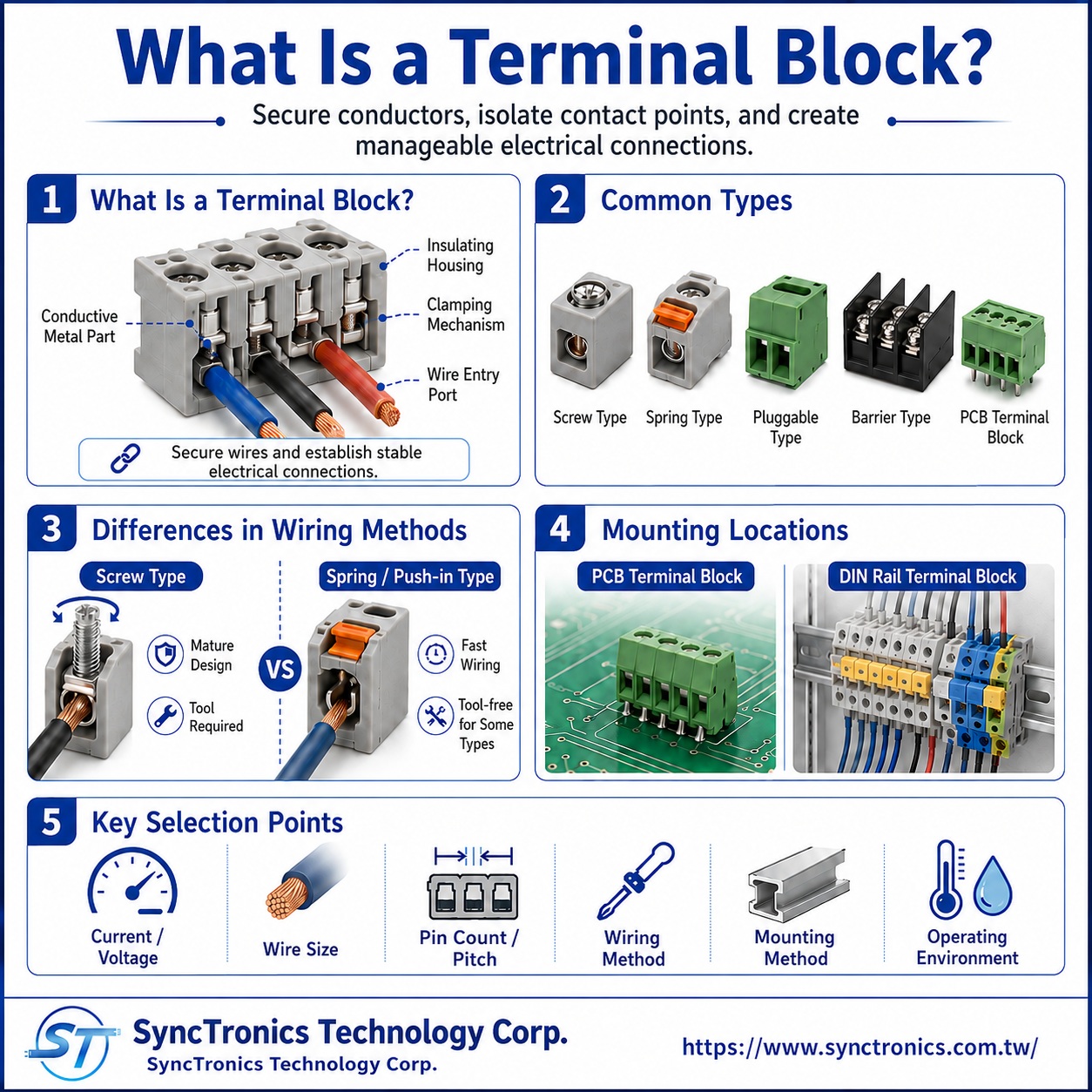
What Is a Terminal Block?
A terminal block can be understood as a component that provides a controlled way to connect one or more conductors to another wire, circuit, or PCB while maintaining mechanical retention and electrical insulation.
A typical terminal block may include:
|
Component |
Main Function |
|
Conductive contact |
Carries current or electrical signals |
|
Insulating housing |
Separates adjacent circuits and reduces short-circuit risk |
|
Wire-clamping mechanism |
Secures the conductor using screws, springs, or other structures |
|
Wire entry |
Provides the position for conductor insertion |
|
PCB pin or mounting structure |
Connects the terminal block to a PCB, rail, or other support |
The exact construction depends on the terminal block family and application.
Are a Terminal and a Terminal Block the Same Thing?
Not exactly.
The terms are sometimes used loosely, but in connector and wire-harness applications they describe different things.
|
Term |
Basic Meaning |
|
Terminal |
An individual conductive contact, such as a crimp terminal |
|
Terminal Block |
An insulated connection assembly containing one or more wiring positions |
|
Connector |
A mating electrical interconnect system, usually designed for plug-and-receptacle connection |
For example, a crimp terminal is typically attached to a wire and inserted into a connector housing. A terminal block often allows a stripped conductor to be secured directly by a screw or spring mechanism.
In simple terms:
A terminal is a conductive contact, while a terminal block is a complete wiring interface.
What Are the Common Types of Terminal Blocks?
Terminal blocks can be classified by their connection and mounting methods.
|
Type |
Main Characteristic |
Common Applications |
|
Screw Terminal Block |
Uses screw-generated clamping force |
Power supplies, control equipment, PCB wiring |
|
Spring / Push-In Terminal Block |
Uses spring force to retain the conductor |
Control cabinets, automation, fast wiring |
|
Barrier Terminal Block |
Provides pronounced insulation barriers between positions |
Power equipment and higher-current wiring |
|
Pluggable Terminal Block |
Separates the wired plug from the PCB header |
Controllers, industrial modules, serviceable equipment |
|
PCB Terminal Block |
Mounts directly to the PCB |
Power boards, control boards, drives |
The best choice depends on how the equipment will be assembled, serviced, and wired.
How Does a Screw Terminal Block Secure a Wire?
Screw terminal blocks use a screw-operated clamping structure to hold the conductor against a conductive contact.
After the insulation is stripped to the specified length, the conductor is inserted into the wiring position and secured by tightening the screw.
Common advantages include:
- Mature and widely used construction
- Support for a broad range of wiring applications
- Straightforward installation
- Suitable for many industrial and power systems
However, the manufacturer’s specified strip length, conductor type, and tightening torque should be followed.
A screw connection is not more reliable simply because it is tightened as much as possible.
Excessive torque can damage the screw, clamping structure, or conductor, while insufficient torque may result in an unstable electrical connection.
What Is the Difference Between Screw and Spring Terminal Blocks?
Spring-clamp and push-in terminal blocks use a spring mechanism rather than relying primarily on screw torque.
Depending on the product design, solid conductors or conductors fitted with ferrules may be inserted directly, while flexible stranded wires may require a release mechanism or tool.
|
Screw Type |
Spring / Push-In Type |
|
Clamping force generated by a screw |
Clamping force generated by a spring |
|
Installation typically requires a tool |
Some designs allow tool-free insertion |
|
Tightening torque must be controlled |
Conductor type and insertion method must be checked |
|
Mature and widely used |
Useful for fast and repeatable wiring |
Neither technology is universally superior. Selection should reflect the equipment design, conductor type, installation process, and maintenance requirements.
What Is a Pluggable Terminal Block?
A pluggable terminal block separates the wire-termination section from the PCB-mounted section.
A typical structure is:
Wire → Pluggable Terminal Block → PCB Header → PCB
The wire can be terminated first, and the complete plug can then be inserted into the PCB header.
This can simplify maintenance because the wiring does not always need to be removed conductor by conductor when a controller or circuit board is replaced.
Typical applications include:
- Industrial controllers
- Power equipment
- Automation modules
- Replaceable control boards
- Serviceable electronic equipment
The plug and header must still be verified for the same series, pitch, pin count, insertion direction, and locking arrangement.
What Is a Barrier Terminal Block?
Barrier terminal blocks use insulating barriers between adjacent connection positions.
Depending on the design, the wiring may be secured with screws, pressure plates, ring terminals, fork terminals, or other termination methods.
This construction is commonly used when:
- Clear separation between circuits is important
- Larger conductors are involved
- More wiring space is needed
- Power connections must be easy to inspect
However, a barrier-style appearance does not define a universal current or voltage rating.
Ratings depend on the specific contact size, spacing, material, conductor range, and product certification.
What Is the Difference Between a PCB Terminal Block and a DIN-Rail Terminal Block?
The primary difference is the mounting location.
|
PCB Terminal Block |
DIN-Rail Terminal Block |
|
Mounted directly to a PCB |
Mounted on a DIN rail or other support structure |
|
Connects external wiring to a circuit board |
Used for wiring distribution inside panels and equipment |
|
Requires PCB footprint and soldering considerations |
Requires rail and panel-layout considerations |
|
Common in power boards and control boards |
Common in control cabinets and automation systems |
A PCB terminal block may itself use screw, spring, push-in, or pluggable termination.
Therefore, PCB terminal block describes the mounting format, not a single wire-clamping technology.
What Does Pitch Mean on a Terminal Block?
Pitch is the center-to-center distance between adjacent connection positions.
It is an important mechanical specification, especially for PCB terminal blocks.
Two 4-position terminal blocks with different pitches may have:
- Different PCB footprints
- Different overall widths
- Different wiring space
- Completely incompatible mounting dimensions
A specification such as:
“4-position terminal block”
is therefore not enough by itself.
At minimum, the design should also confirm:
Pin count + pitch + termination method + PCB mounting dimensions
How Do You Select a Terminal Block?
Terminal block selection can be organized into six main areas.
|
Selection Factor |
What to Confirm |
|
Electrical requirements |
Operating voltage, current, and circuit function |
|
Conductor requirements |
AWG or cross-sectional area, solid or stranded conductor |
|
Wiring method |
Screw, spring, push-in, pluggable, or other termination |
|
Mechanical dimensions |
Pin count, pitch, height, wire-entry direction, available space |
|
Mounting method |
PCB, DIN rail, panel, or other mounting structure |
|
Operating environment |
Vibration, temperature, humidity, maintenance, and service needs |
Current and voltage ratings should not be estimated from appearance or pitch alone.
Two terminal blocks with the same pitch can have very different contact structures, materials, conductor ranges, and certified ratings.
The final decision should be based on the exact product specification.
Can a Wire Be Inserted Directly into Any Terminal Block?
No. It depends on the terminal block design and conductor type.
Possible conductor configurations include:
- Solid wire
- Stranded wire
- Fine-stranded flexible wire
- Wire with a ferrule
- Wire terminated with a ring or fork terminal
Different clamping systems have different conductor preparation requirements.
Some push-in terminal blocks allow direct insertion of certain conductor types, while barrier or stud-style products may be designed for ring or fork terminals.
Manufacturer wiring instructions should therefore be followed rather than applying one termination method to every terminal block.
Is a Higher Current Rating Always Better?
No.
A higher current rating may require:
- Larger contacts
- Larger pitch
- More PCB area
- Larger conductors
- More installation space
- Higher component cost
If the application carries only a small control current, an oversized terminal block may unnecessarily increase space and cost.
For higher-current applications, the terminal block rating should also be evaluated together with:
Wire size, PCB copper, solder joints, ambient temperature, and actual load conditions.
The goal is to select a terminal block that meets the real electrical requirements with appropriate design margin, rather than simply choosing the highest possible rating.
Common Terminal Block Selection Misunderstandings
|
Common Assumption |
Correct Understanding |
|
Same pin count means interchangeable |
Pitch, dimensions, footprint, and termination must also match |
|
Tighter screw torque is always better |
Tightening should follow the manufacturer specification |
|
The terminal block current rating defines the whole system current |
Wire, PCB, solder joints, and environment must also be considered |
|
Any flexible wire can be inserted directly |
Conductor preparation depends on the clamping system |
|
All PCB terminal blocks use screws |
PCB terminal blocks may also use spring, push-in, or pluggable designs |
|
A terminal and a terminal block are the same component |
A terminal is a contact; a terminal block is a complete wiring interface |
Summary
A terminal block is a wiring component used to secure conductors, maintain electrical isolation, and create a reliable electrical connection. It may connect wires to other conductors or provide a direct interface between external wiring and a PCB.
Common designs include screw, spring or push-in, barrier, pluggable, and PCB terminal blocks.
The correct choice should consider voltage, current, conductor size, pin count, pitch, wiring method, mounting structure, and operating environment.
Rather than selecting by appearance alone, the exact product part number and manufacturer specifications should be used to confirm compatibility and ratings.
SyncTronics Solutions
SyncTronics Technology can support terminal block selection for power supplies, control boards, industrial equipment, and other electronic systems by assisting with the evaluation of pin count, pitch, conductor size, current and voltage ratings, wiring direction, and PCB mounting requirements.
Available terminal block solutions include barrier-type, PCB screw-type, pluggable, and related configurations. Support is also available for specification review, alternative part evaluation, NPI projects, and electronic interconnect supply chain integration based on actual application requirements.
Need Wire Harnesses, Connectors, Electromechanical Components, or Custom Solutions? Contact Us Today
Whether you are looking for connectors, cables, wire harness assemblies, electromechanical components, or complete electronic interconnect solutions, SyncTronics provides professional technical support and engineering evaluation for product selection, specification verification, New Product Introduction (NPI), OEM/ODM customization, as well as high-speed transmission, high-reliability, and other specialized application requirements.
We welcome you to visit our Contact Us page and share your project requirements and contact information. Our team is committed to responding quickly and professionally, evaluating the most suitable products and electronic interconnect solutions based on your product specifications, application requirements, and project objectives. We also provide technical recommendations and customized engineering support to help shorten product selection and development time, reduce project risks, and accelerate your path to mass production. We look forward to the opportunity to work with you and provide reliable technical support and practical solutions for every stage of your project.
Related Articles
What Is Connector Pitch? Complete Guide | SyncTronics Technology
What Is Connector Pin Count? Complete Guide | SyncTronics Technology
Terminal vs Connector vs Header: Differences Explained | SyncTronics Technology
What Is Contact Resistance? Complete Guide | SyncTronics Technology
What Is Retention Force? Complete Guide | SyncTronics Technology
Disclaimer and Technical Exchange Statement
This content is compiled based on publicly available information and industry experience, intended solely for reference during technical exchanges. It does not constitute any commercial, technical, or legal advice or basis.
The specifications, materials, manufacturing processes, application methods, and related information described herein may vary due to differing design conditions, environmental factors, or usage scenarios. No guarantees are made regarding the completeness, correctness, or suitability of such content.
Readers should verify the suitability with the responsible design or technical personnel based on actual application scenarios, and independently assess all associated risks.
Frequently Asked Questions (FAQ)
- What is Connector Knowledge
- What Is a Connector?
- Euro-Style vs. Barrier Terminal Blocks
- Ring vs. Fork Terminals: Differences
- What Is an IDC Connector?
- Box Header vs. Ejector Header: Latching, Ejection, and When to Use Each
- What Is a Box Header?
- 6 Common Connector Selection Mistakes and How to Avoid Them
- How to Select a USB Type-C Connector: Mating Cycles, Current Rating & PCB Mounting
- How to Select Industrial Automation Connectors: Locking, Vibration Resistance & Retention
- How to Select Energy Storage Connectors: Current Rating, Contact Resistance & Keying
- Why Do High-Current Connectors Overheat? Contact Resistance, Terminals & Crimp Quality
- What Is a Terminal Block? Types, Structure & Selection
- Wire-to-Board vs. Board-to-Board Connectors: Structure and Selection
- How to Select Drone Connectors and Wire Harnesses: Power, Flight Controller, GPS and Signal Connections
- What Connectors Are Commonly Used in Drones? XT30, XT60, JST-GH, and DF13 Explained
- How to Select Drone Battery Connectors: XT30, XT60 and XT90
- Why Do Drone Connectors Become Loose? Vibration Resistance, Polarization and Retention Design
- RJ45 Connector Structure and Applications Guide
- What Is Connector Pitch?
- What Does Connector Pin Count Mean?
- What Is the Difference Between a Terminal, a Connector, and a Coupling?
- What Is Contact Resistance, and What Does It Affect?
- What Is Connector Insertion and Withdrawal Force?
- What Is Retention Force?
- What Is Poka-Yoke (Error-Proofing) Design?
- What Is Gold Plating Thickness? Why Does It Affect Connector Lifespan?
- What Is the Difference Between SMT Connectors and DIP Connectors?
- Wire Related issues
- Materials-Related
- Regulatory Issues
- Electronic issues
- Manufacturing Technology
- Testing & Verification
- Quality Management
- History & Evolution