
How to Choose AWG Wire Size for Drone Power Cables
Choosing the right AWG wire size for a drone power cable should not be based on maximum current alone. A proper design needs to consider continuous current, peak current, total circuit length, allowable voltage drop, temperature rise, ambient conditions, connector compatibility, and aircraft weight. In general, a lower AWG number means a larger conductor with lower resistance, but it also adds weight, diameter, and mechanical stiffness.
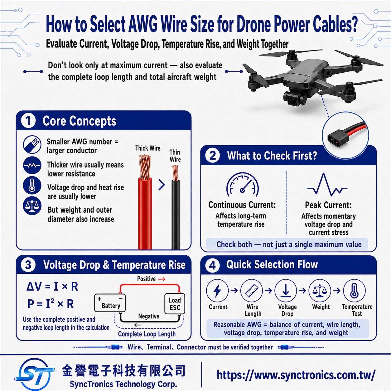
Why Do Larger Wires Usually Reduce Voltage Drop and Heat?
AWG, or American Wire Gauge, defines conductor size. As the AWG number decreases, conductor cross-sectional area increases. For the same conductor material and length, a larger conductor generally has lower electrical resistance.
The table below illustrates the approximate resistance difference between several common copper wire sizes at 20°C.
|
AWG |
Approx. DC Resistance |
General Trade-Off |
|
10 AWG |
3.28 mΩ/m |
Very low resistance, but heavier and larger |
|
12 AWG |
5.21 mΩ/m |
Suitable for evaluating higher-current circuits |
|
14 AWG |
8.28 mΩ/m |
Balanced resistance and weight |
|
16 AWG |
13.18 mΩ/m |
Lighter, but voltage drop increases at higher current |
|
18 AWG |
20.95 mΩ/m |
Lightweight, but requires careful current and length evaluation |
|
20 AWG |
33.30 mΩ/m |
More suitable for lower-current circuits |
These values are useful for comparing conductor resistance, but they are not a universal ampacity chart for drone wiring.
Actual drone cables may use stranded conductors, tinned copper, different strand counts, and different insulation systems. The final design should therefore be checked against the specifications of the actual wire being used.
Should Drone Wire Sizing Be Based on Continuous or Peak Current?
Both matter, but for different reasons.
Continuous current primarily determines long-term conductor heating and is one of the main factors used to determine whether a wire can operate safely over time.
Peak current becomes important during conditions such as takeoff, rapid acceleration, high motor load, or sudden power demand. These short-duration events can cause additional voltage drop and electrical stress.
A drone power cable should therefore be evaluated using at least:
- Normal operating or cruise current
- Continuous current under the expected load
- Peak current during acceleration or full-power operation
- Duration of peak-current events
- Actual cable length between the battery and load
- Battery, power distribution board, ESC, and connector specifications
- Ambient temperature and cooling conditions
Using only the motor rating or battery discharge rating is not enough to determine the correct AWG size.
How Do You Calculate Voltage Drop in a Drone Power Cable?
Voltage drop can be estimated using Ohm's law:
Voltage Drop (ΔV) = Current (I) × Circuit Resistance (R)
The important point is that the resistance calculation must include the complete current path.
For example, if the distance from the battery to the load is 0.5 meter, the positive conductor is approximately 0.5 meter and the return conductor is also approximately 0.5 meter. The resistance calculation should therefore use approximately 1 meter of total conductor length.
Power dissipated in the wire can be estimated as:
Power Loss (P) = I² × R
This relationship is particularly important in high-current drone systems because resistive heating increases with the square of the current.
For example, assume:
- Continuous current: 20 A
- One-way battery-to-load distance: 0.5 m
- Total positive and return conductor length: approximately 1 m
Using conductor resistance only for comparison:
|
AWG |
Approx. Circuit Voltage Drop |
Approx. Conductor Power Loss |
|
10 AWG |
0.066 V |
1.31 W |
|
12 AWG |
0.104 V |
2.08 W |
|
14 AWG |
0.166 V |
3.31 W |
|
16 AWG |
0.264 V |
5.27 W |
This table does not mean that every wire size shown is suitable for continuously carrying 20 A.
It only demonstrates how higher conductor resistance increases both voltage drop and I²R losses under the same current and cable length.
The actual acceptable AWG must still be confirmed against the wire construction, insulation rating, ambient temperature, bundling, airflow, and manufacturer specifications.
Why Can't You Simply Use an "AWG vs. Amps" Chart?
Because current-carrying capacity is not determined by AWG alone.
Two cables with the same AWG can have different allowable current levels depending on:
- Individual wire versus bundled installation
- Open-air versus enclosed installation
- Ambient temperature
- Insulation temperature rating
- Conductor material and plating
- Continuous operating time
- Airflow and cooling
- Nearby heat sources such as motors or ESCs
- Harness routing and installation density
This is why a generic statement such as "18 AWG supports X amps" should not be treated as a universal rule unless the applicable test conditions and standard are clearly defined.
For drone applications, actual installation conditions matter.
Does Using a Larger Wire Always Make a Drone More Reliable?
Not necessarily.
A larger conductor can reduce electrical resistance, voltage drop, and resistive heating, but it can also increase:
- Copper weight
- Cable diameter
- Minimum bend radius
- Mechanical load near connectors
- Harness stiffness
- Routing space requirements
- Connector and terminal size requirements
Weight is especially important in drones because unnecessary wiring mass can affect payload capacity, flight time, and overall efficiency.
The best wire is therefore not simply the largest conductor that can physically fit.
A better design target is:
Use a conductor large enough to meet electrical, thermal, mechanical, and reliability requirements without adding unnecessary weight.
Reducing unnecessary cable length can also lower resistance and weight, and in some cases provides a better system-level improvement than simply increasing every conductor size.
Why Should Temperature Rise Be Verified in the Actual System?
Resistance calculations are useful for initial wire selection, but they do not fully represent the thermal environment inside the aircraft.
A drone may contain several heat sources at the same time, including:
- Battery cells
- Electronic Speed Controllers (ESCs)
- Motors
- Power distribution electronics
- Enclosed compartments
- Bundled power cables
As conductor temperature rises, conductor resistance also increases. This can further increase voltage drop and reduce electrical efficiency.
Prototype testing should therefore evaluate the system under actual or near-worst-case operating conditions.
Useful measurements include:
- Battery-side voltage
- Load-side voltage
- Cable temperature
- Connector temperature
- Terminal or solder-joint temperature
- Temperature after sustained high-load operation
The wire itself should not be evaluated in isolation. The complete power path includes the conductor, terminals, solder joints, connectors, and power-distribution components.
Connector and Terminal Selection Can Also Limit AWG Size
A larger AWG wire cannot always be installed simply because the electrical calculation suggests using a larger conductor.
The selected connector or terminal must support the wire's:
- Conductor size range
- Crimp range
- Solder-cup dimensions
- Insulation diameter
- Cable exit direction
- Strain-relief requirements
Using a wire that is too large for the terminal may result in improper crimping, assembly difficulties, excessive stiffness, or mechanical stress at the connector.
Using a wire that is too small can also create problems such as poor crimp compression, insufficient pull strength, or inadequate electrical performance.
For this reason, the wire, terminal, and connector should be treated as one complete current-carrying system.
Practical AWG Selection Process for Drone Power Wiring
A practical selection process should follow this logic:
- Determine continuous operating current
- Determine peak current and peak duration
- Calculate the total positive and return conductor length
- Define the maximum acceptable voltage drop
- Compare the resistance of candidate AWG sizes
- Evaluate ambient temperature, bundling, and cooling conditions
- Confirm connector and terminal wire-size compatibility
- Compare cable diameter and actual weight
- Build a prototype harness
- Measure voltage drop and temperature rise under load
- Finalize the conductor size after validation
This approach is more reliable than selecting a wire from a generic AWG current chart alone.
Common Drone Power Wire Sizing Mistakes
Selecting Wire Based Only on Maximum Current
Current alone does not account for cable length, peak duration, ambient temperature, or installation conditions.
Calculating Only the One-Way Cable Length
A DC circuit includes both the supply and return paths. Ignoring the return conductor underestimates total resistance and voltage drop.
Reducing AWG Size Only to Save Weight
A smaller conductor may reduce aircraft weight, but it also increases resistance, voltage drop, and temperature rise.
Using Oversized Wire Everywhere
Oversizing every power conductor increases weight, stiffness, space requirements, and mechanical load without necessarily improving overall system performance.
Upgrading the Connector but Ignoring the Wire
The performance of the complete power path depends on the conductor, terminal, connector, solder joint, and power-distribution structure. The weakest part can limit the entire circuit.
Skipping Temperature-Rise Validation
Calculations are useful for initial design, but the final harness should still be tested under representative operating conditions.
Summary
Selecting AWG wire size for drone power cables requires balancing current, cable length, voltage drop, temperature rise, and weight rather than relying on a single AWG-to-current chart.
A larger conductor reduces resistance and power loss but increases weight, diameter, and routing stiffness. A smaller conductor saves weight but can increase voltage drop and heating.
The most practical approach is to use continuous and peak current, total circuit length, and allowable voltage drop to identify candidate AWG sizes, then verify actual cable specifications, connector compatibility, and temperature rise under realistic load conditions. This provides a better balance between electrical reliability and aircraft weight.
SyncTronics Solutions
SyncTronics Technology can support drone power cable and wire harness projects by evaluating conductor size, cable length, current requirements, weight restrictions, connector compatibility, and installation space as part of an integrated electronic interconnect solution.
For prototype and NPI projects, customers can provide battery specifications, continuous and peak current requirements, cable lengths, connector part numbers, pin assignments, and mechanical constraints. SyncTronics can assist with wire selection, connector and terminal matching, harness configuration, special pinouts, alternative part evaluation, OEM/ODM project coordination, and supply chain integration based on the actual application requirements.
Need Wire Harnesses, Connectors, Electromechanical Components, or Custom Solutions? Contact Us Today
Whether you are looking for connectors, cables, wire harness assemblies, electromechanical components, or complete electronic interconnect solutions, SyncTronics provides professional technical support and engineering evaluation for product selection, specification verification, New Product Introduction (NPI), OEM/ODM customization, as well as high-speed transmission, high-reliability, and other specialized application requirements.
We welcome you to visit our Contact Us page and share your project requirements and contact information. Our team is committed to responding quickly and professionally, evaluating the most suitable products and electronic interconnect solutions based on your product specifications, application requirements, and project objectives. We also provide technical recommendations and customized engineering support to help shorten product selection and development time, reduce project risks, and accelerate your path to mass production. We look forward to the opportunity to work with you and provide reliable technical support and practical solutions for every stage of your project.
Related Articles
How to Select Drone Wires: Lightweight, Flexible, Heat-Resistant and Waterproof | SyncTronics Technology
What Is AWG Wire Gauge? Complete Guide | SyncTronics Technology
How to Select Drone Battery Connectors: XT30, XT60 and XT90 | SyncTronics Technology
Drone Connectors: XT30, XT60, JST-GH and DF13 | SyncTronics Technology
Disclaimer and Technical Exchange Statement
This content is compiled based on publicly available information and industry experience, intended solely for reference during technical exchanges. It does not constitute any commercial, technical, or legal advice or basis.
The specifications, materials, manufacturing processes, application methods, and related information described herein may vary due to differing design conditions, environmental factors, or usage scenarios. No guarantees are made regarding the completeness, correctness, or suitability of such content.
Readers should verify the suitability with the responsible design or technical personnel based on actual application scenarios, and independently assess all associated risks.
Frequently Asked Questions (FAQ)
- What is Connector Knowledge
- Wire Related issues
- What Is Wire Harness Assembly? Complete Guide to the Process, Applications, and Benefits
- 60W vs. 100W vs. 140W vs. 240W USB-C Cables: What's the Difference?
- Are All USB-C Cables the Same?
- Solar vs. Energy Storage Cables: Weather Resistance, Voltage & Selection Guide
- What Is a BMS Wire Harness? Cell Voltage, Temperature Sensing & Balancing Explained
- How to Select Energy Storage Power Wire Harnesses: Current, Voltage, Temperature Rise & Flame Retardancy
- What Is Silicone Wire? High-Temperature Properties, Structure & Selection
- How to Choose AWG Wire Size for Drone Power Cables
- How to Select Drone Wires: Lightweight Design, Flexibility, Heat Resistance and Waterproofing
- What Is a High-Speed Transmission Cable?
- What Is a Twisted Pair Cable? Why Does It Reduce Electromagnetic Interference?
- Industrial Cable Applications Explained: How to Select High Temperature, Waterproof, and High Reliability Cables
- What Are the Steps in Wire Processing? Complete Guide to the Manufacturing Process
- What Are Wire Cutting, Wire Stripping, Crimping, and Assembly?
- What Is a High Temperature Cable?
- What Is an Oil-Resistant and Abrasion-Resistant Cable?
- What Is a Waterproof Cable?
- What Are UL-Rated Wires?
- What Is AWG Wire Gauge? How Do You Choose the Right Wire Size?
- What Is a Controlled Impedance Cable?
- What Is a Differential Signal Cable?
- What Is a High Frequency Cable?
- What Is the Difference Between a Coaxial Cable and a Ribbon Cable?
- Older Network Cable Versions Explained: What Are CAT3, CAT4, and CAT5?
- CAT5e vs CAT6 vs CAT6a vs CAT7 vs CAT8 Complete Guide
- STP vs UTP Ethernet Cables: Understanding Shielded and Unshielded Twisted Pair Differences
- What Are the Differences Between USB, HDMI, D-Sub, and LVDS Cables?
- Materials-Related
- Regulatory Issues
- Electronic issues
- Manufacturing Technology
- Testing & Verification
- Quality Management
- History & Evolution