
Why Do High-Current Connectors Overheat? Contact Resistance, Terminals & Crimp Quality
A high-current connector may experience some temperature rise during normal operation, but one terminal becoming unusually hot, housing discoloration or deformation, burned contacts, odor, or melting can indicate an abnormal resistance or thermal problem somewhere in the current path.
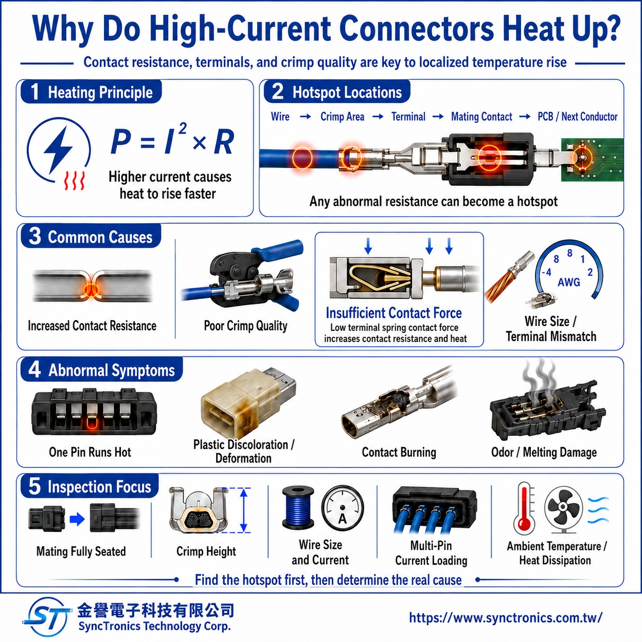
The basic principle is Joule heating:
Power loss P = I² × R
As current increases, heat generated by resistance rises with the square of the current. In high-current systems, even a very small increase in contact resistance can therefore create significant localized heating.
Where Does Heat Come From in a High-Current Connector System?
The electrical path includes more than the connector itself.
A simplified current path is:
Wire → Crimp Area → Terminal → Mating Contact → Terminal / PCB or Next Wire
Abnormal resistance at any point can become a localized heat source.
|
Heat Source |
Common Causes |
|
Wire |
Undersized conductor, damaged strands, poor heat dissipation |
|
Crimp area |
Under-crimping, over-crimping, missing strands, incomplete conductor insertion |
|
Mating contact |
Low contact force, contamination, oxidation, wear |
|
Terminal body |
Insufficient cross-section or inappropriate terminal design |
|
PCB termination |
Soldering problems or insufficient PCB copper capacity |
|
Complete connector |
Multiple loaded pins, high ambient temperature, restricted airflow |
When a connector overheats, it is therefore important to identify the actual hot spot before assuming that the connector current rating is too low.
Why Does Contact Resistance Cause Connector Heating?
When two metal contacts mate, the apparent contact area may look large, but electrical current actually flows through many microscopic contact points.
Contact performance is influenced by:
- Contact force
- Effective contact area
- Terminal material
- Surface plating
- Oxidation and corrosion
- Dust or contamination
- Mating wear
- Terminal deformation
- Whether the connector is fully mated
If the effective contact area decreases or contact force becomes insufficient, contact resistance can increase.
In low-current signal applications, a small resistance increase may have limited thermal impact. In a high-current path, however, the I²R relationship makes the same resistance increase much more significant.
Why Do a Few Milliohms Matter at High Current?
Consider a simplified example where an additional contact resistance is:
5 mΩ = 0.005 Ω
At 10 A:
P = 10² × 0.005 = 0.5 W
At 30 A:
P = 30² × 0.005 = 4.5 W
The resistance is unchanged, but increasing current by three times increases resistive power loss by nine times.
This is why high-current connector design places strong emphasis on:
Low and stable contact resistance
This example only illustrates the electrical principle. Actual contact temperature also depends on thermal dissipation, ambient temperature, wire size, housing construction, and surrounding components.
Why Can Poor Crimp Quality Cause Overheating?
A crimp terminal must do more than mechanically hold the wire.
Its primary electrical function is to create a stable terminal-to-conductor interface.
If the crimp is too loose, the conductor and terminal may not form sufficient electrical contact.
If the crimp is excessive, conductor strands or the terminal itself may be damaged.
|
Crimp Problem |
Possible Result |
|
Crimp height too high |
Insufficient conductor compression and higher resistance |
|
Crimp height too low |
Excessive conductor deformation or strand damage |
|
Missing conductor strands |
Reduced effective conductor cross-section |
|
Strands damaged during stripping |
Reduced electrical and mechanical strength |
|
Conductor not fully inserted |
Insufficient crimp contact area |
|
Insulation inside conductor crimp |
Reduced metal-to-conductor contact |
|
Terminal and wire mismatch |
Incorrect crimp geometry |
|
Worn or misaligned tooling |
Unstable crimp dimensions and compression |
For this reason:
A wire passing a simple pull check does not automatically prove that the electrical quality of the crimp is acceptable.
Mechanical retention and electrical performance are related, but they are not identical evaluation criteria.
Does a Tighter Crimp Always Reduce Resistance?
No.
This is a common misunderstanding.
A proper crimp requires controlled plastic deformation of the terminal and conductor to create a stable mechanical and electrical connection.
An under-crimp can result in insufficient contact, but an over-crimp can also cause:
- Excessive conductor compression
- Broken strands
- Terminal barrel deformation
- Stress concentration
- Reduced long-term fatigue reliability
Crimp height should therefore not simply be reduced in an attempt to lower resistance.
The correct crimp specification should be based on:
Exact terminal part number + Wire specification + Conductor construction + Manufacturer crimp requirements
Can an Incompletely Mated Connector Overheat?
Yes.
If the connector halves are not fully mated, the contacts may operate outside their intended mating position.
This can result in:
- Reduced effective contact area
- Abnormal contact force
- Increased contact resistance
- Incomplete latch engagement
- Further loosening under vibration
For high-current connectors, it is important to verify:
Correct terminal seating + Full housing engagement + Proper lock engagement
If the connector uses a secondary lock, terminal position assurance feature, or other retention mechanism, it should also be assembled according to the intended design.
Why Is Contact Force Important?
When male and female terminals mate, the elastic contact structure must maintain sufficient force at the interface.
If contact force becomes too low, the electrical interface can degrade.
|
Possible Cause |
Potential Effect |
|
Terminal deformation |
Contact no longer operates at the designed position |
|
Repeated mating wear |
Contact surface and spring behavior change |
|
Incorrect mating component |
Contact geometry does not match |
|
Long-term elevated temperature |
Stress relaxation may reduce contact force |
|
Vibration |
Micromotion may occur at the contact interface |
|
External pulling force |
Terminal or housing position may shift |
Current capability therefore depends on more than simply how thick the metal terminal is. The contact geometry and spring performance are also critical.
Does Plating Affect High-Current Connector Heating?
It can, but the relationship is not as simple as saying that gold plating always runs cooler.
Common connector contact finishes include:
- Tin
- Gold
- Silver
- Nickel underplates
Plating mainly affects the contact interface by influencing:
- Oxidation
- Corrosion
- Friction and wear
- Contact stability
- Service life
Different current levels, mating cycles, environments, and contact structures may require different plating systems.
If a high-current contact experiences wear, contamination, or corrosion, contact resistance may gradually increase and contribute to higher localized temperature.
The correct evaluation therefore considers plating specification together with the actual contact design and application.
Can an Undersized Wire Make the Connector Appear to Overheat?
Yes.
Sometimes the primary heat source is not the mating contact itself but the wire close to the connector.
If the conductor cross-section is too small:
Higher conductor resistance → Higher wire temperature → Heat transfers into the terminal and connector
The entire connector area may then appear hot.
This is why a high-current system should be evaluated as a complete path:
Wire → Crimp → Terminal → Connector
rather than as isolated components.
If a Connector Is Rated for 30 A, Can It Always Carry 30 A Continuously?
No.
A manufacturer’s current rating is typically established under specific product and test conditions.
Those conditions may include:
- Specified terminals
- Specified wire gauge
- Specified number of loaded contacts
- Specified ambient temperature
- Defined temperature-rise criteria
- Specified mounting method
- Specified housing
- Defined test method
If the actual application uses a smaller wire, multiple adjacent contacts at high load, an enclosed housing, or higher ambient temperature, the real temperature rise may be different.
Therefore:
Current rating is not an absolute number independent of operating conditions.
The complete product specification should always be reviewed.
Does It Matter If Several Pins Carry High Current at the Same Time?
Yes.
The thermal behavior of a single loaded contact may differ from several adjacent contacts carrying high current simultaneously.
When multiple pins generate heat at the same time, heat can accumulate inside the connector and influence neighboring terminals.
Actual temperature rise may depend on:
- Pin configuration
- Housing size
- Wire gauge
- PCB copper area
- Airflow
- Enclosure design
- Nearby heat sources
A single-contact current rating should therefore not automatically be interpreted as the current capability of every pin operating at full load unless the manufacturer explicitly supports that condition.
Why Does Ambient Temperature Matter?
The final operating temperature can be simplified as:
Ambient temperature + Current-induced temperature rise
A connector operating at 25°C ambient and the same connector operating at 70°C ambient may experience the same temperature rise, but their final material temperatures will be very different.
A connector system also includes:
- Plastic housing
- Seals
- Wire insulation
- PCB
- Nearby components
High-current connector selection should therefore consider both current and ambient temperature.
How Can You Troubleshoot an Overheating High-Current Connector?
A practical starting point is to identify where the hot spot occurs.
|
Heating Pattern |
Priority Inspection Area |
|
One pin is much hotter than the others |
Contact resistance, deformation, contamination, crimp |
|
All loaded pins are warm |
Load level, connector sizing, thermal environment |
|
Wire near terminal is hottest |
Wire gauge, conductor damage, crimp condition |
|
Mating interface is hottest |
Engagement, contact force, contact wear |
|
PCB side is hottest |
Solder joint, PCB copper, board-side current path |
|
Heating develops after long-term use |
Wear, oxidation, corrosion, loosening, aging |
This approach is usually more useful than immediately replacing the connector with a larger one without identifying the actual cause.
How Can You Verify Whether Contact Resistance Is Causing the Heating?
Engineering evaluation may include:
|
Verification Method |
What It Can Reveal |
|
Visual inspection |
Discoloration, burn marks, terminal back-out, housing deformation |
|
Contact resistance measurement |
Abnormal resistance at the contact interface |
|
Voltage drop measurement |
Electrical loss across a section of the current path under load |
|
Temperature-rise observation |
Location of localized heating |
|
Crimp dimension check |
Whether the crimp meets specified geometry |
|
Pull testing |
Mechanical retention of the crimp |
Milliohm-level resistance measurements can be strongly affected by test leads and probe contact resistance, so an appropriate low-resistance measurement method is typically required.
Also, a connector that shows continuity or appears to have a normal temperature under one condition is not automatically proven to meet all electrical reliability requirements.
Is Temperature Rise the Same as Maximum Connector Temperature?
No.
These are different concepts.
Temperature rise:
How much the connector temperature increases above the surrounding ambient
temperature due to electrical load.
Maximum operating temperature:
The allowable operating temperature range of the connector materials and
construction.
A connector housing capable of withstanding a high temperature does not mean the connector can safely tolerate unlimited current-induced temperature rise.
The engineering relationship should be evaluated as:
Ambient temperature + Electrical temperature rise ≤ Allowable operating condition
Plastic heat resistance alone cannot determine current capability.
Can an Overheated Connector Continue to Be Used?
If a connector has already experienced significant overheating, discoloration, melting, burn marks, or contact damage, the cause should be investigated before continued use.
Excessive heat may have altered:
- Terminal spring properties
- Contact surfaces
- Plating condition
- Plastic housing
- Crimp area
- Wire insulation
Once the contact interface is degraded, resistance can increase further and create a thermal feedback cycle:
Higher resistance → More heat → Further contact degradation
Affected components may therefore require replacement after the failure mechanism has been identified.
What Should Be Checked When Selecting a High-Current Connector?
A practical evaluation can be organized into six areas:
|
Evaluation Area |
What to Confirm |
|
Current |
Continuous current, peak current, load duration |
|
Terminal |
Contact design, material, cross-section, rated conditions |
|
Wire |
AWG / cross-section, conductor construction, cable length |
|
Crimp |
Terminal-to-wire compatibility, crimp height, process requirements |
|
Environment |
Temperature, vibration, contamination, corrosion, cooling |
|
System |
Pin count, adjacent loaded contacts, PCB and overall power distribution |
The correct question is not simply:
“What is the connector’s current rating?”
A better engineering evaluation considers the complete system:
Connector + Terminal + Wire + Termination + Environment
Common Misunderstandings About High-Current Connector Heating
|
Common Assumption |
Correct Understanding |
|
Any heating means the connector is defective |
Some temperature rise is normal; the issue is excessive or localized heating |
|
A 30 A connector can carry 30 A under any condition |
Current capability depends on wire size, temperature, pin loading, and test conditions |
|
Electrical continuity means the contact is good |
Continuity and low, stable contact resistance are not the same thing |
|
A tighter crimp always lowers resistance |
Excessive crimping can damage both conductor and terminal |
|
A large wire guarantees the connector will stay cool |
The terminal, contact interface, and crimp can still create localized resistance |
|
Higher-temperature plastic solves overheating |
Heat-resistant materials do not replace proper current-path and contact design |
Summary
High-current connector heating is fundamentally caused by electrical power loss as current flows through resistance in conductors and contact interfaces.
Because resistive heating increases with the square of current, even a small increase in contact resistance, crimp resistance, or conductor resistance can create significant localized temperature rise in high-current applications.
The complete current path should be evaluated:
Wire → Crimp → Terminal → Mating Contact → PCB or Next Conductor
Terminal contact force, plating, mating condition, wire size, crimp quality, multiple loaded pins, ambient temperature, and heat dissipation can all influence final operating temperature.
High-current connector selection should therefore not rely only on the advertised current rating. A more reliable approach is to evaluate continuous and peak current, wire size, terminal design, load profile, ambient conditions, manufacturer specifications, voltage drop, contact resistance, and temperature rise as a complete system.
SyncTronics Solutions
SyncTronics Technology can support power connector, high-current terminal, and high-current wire harness projects by assisting with the evaluation of connector, terminal, wire, and termination compatibility, including current rating, AWG wire size, terminal structure, contact resistance, crimp requirements, ambient temperature, and available installation space.
For NPI, OEM/ODM, and customized electronic interconnect projects, SyncTronics can also support specification review based on product drawings, current requirements, connector and terminal part numbers, and wire harness specifications, together with alternative part evaluation and supply chain integration. Where projects include specific temperature-rise, contact-resistance, or other validation requirements, relevant validation conditions and external testing resources can be coordinated according to customer specifications. Final current capability should always be confirmed against the complete manufacturer specification and actual application conditions.
Need Wire Harnesses, Connectors, Electromechanical Components, or Custom Solutions? Contact Us Today
Whether you are looking for connectors, cables, wire harness assemblies, electromechanical components, or complete electronic interconnect solutions, SyncTronics provides professional technical support and engineering evaluation for product selection, specification verification, New Product Introduction (NPI), OEM/ODM customization, as well as high-speed transmission, high-reliability, and other specialized application requirements.
We welcome you to visit our Contact Us page and share your project requirements and contact information. Our team is committed to responding quickly and professionally, evaluating the most suitable products and electronic interconnect solutions based on your product specifications, application requirements, and project objectives. We also provide technical recommendations and customized engineering support to help shorten product selection and development time, reduce project risks, and accelerate your path to mass production. We look forward to the opportunity to work with you and provide reliable technical support and practical solutions for every stage of your project.
Related Articles
What Is Contact Resistance? Complete Guide | SyncTronics Technology
What Is Contact Resistance Testing? Measurement Principles and Standards | SyncTronics Technology
What Is a Pull Test? Wire Harness Tensile Testing Guide | SyncTronics Technology
Disclaimer and Technical Exchange Statement
This content is compiled based on publicly available information and industry experience, intended solely for reference during technical exchanges. It does not constitute any commercial, technical, or legal advice or basis.
The specifications, materials, manufacturing processes, application methods, and related information described herein may vary due to differing design conditions, environmental factors, or usage scenarios. No guarantees are made regarding the completeness, correctness, or suitability of such content.
Readers should verify the suitability with the responsible design or technical personnel based on actual application scenarios, and independently assess all associated risks.
Frequently Asked Questions (FAQ)
- What is Connector Knowledge
- What Is a Connector?
- Euro-Style vs. Barrier Terminal Blocks
- Ring vs. Fork Terminals: Differences
- What Is an IDC Connector?
- Box Header vs. Ejector Header: Latching, Ejection, and When to Use Each
- What Is a Box Header?
- 6 Common Connector Selection Mistakes and How to Avoid Them
- How to Select a USB Type-C Connector: Mating Cycles, Current Rating & PCB Mounting
- How to Select Industrial Automation Connectors: Locking, Vibration Resistance & Retention
- How to Select Energy Storage Connectors: Current Rating, Contact Resistance & Keying
- Why Do High-Current Connectors Overheat? Contact Resistance, Terminals & Crimp Quality
- What Is a Terminal Block? Types, Structure & Selection
- Wire-to-Board vs. Board-to-Board Connectors: Structure and Selection
- How to Select Drone Connectors and Wire Harnesses: Power, Flight Controller, GPS and Signal Connections
- What Connectors Are Commonly Used in Drones? XT30, XT60, JST-GH, and DF13 Explained
- How to Select Drone Battery Connectors: XT30, XT60 and XT90
- Why Do Drone Connectors Become Loose? Vibration Resistance, Polarization and Retention Design
- RJ45 Connector Structure and Applications Guide
- What Is Connector Pitch?
- What Does Connector Pin Count Mean?
- What Is the Difference Between a Terminal, a Connector, and a Coupling?
- What Is Contact Resistance, and What Does It Affect?
- What Is Connector Insertion and Withdrawal Force?
- What Is Retention Force?
- What Is Poka-Yoke (Error-Proofing) Design?
- What Is Gold Plating Thickness? Why Does It Affect Connector Lifespan?
- What Is the Difference Between SMT Connectors and DIP Connectors?
- Wire Related issues
- Materials-Related
- Regulatory Issues
- Electronic issues
- Manufacturing Technology
- Testing & Verification
- Quality Management
- History & Evolution