
What Are Drone Flight Controller Cables? GPS, CAN, UART, I²C and PWM Wiring Guide
What Are Drone Flight Controller Cables? GPS, CAN/DroneCAN, UART, I²C and PWM Wiring Explained
A drone flight controller acts as the central control unit of the aircraft and communicates with GPS/GNSS receivers, compasses, electronic speed controllers, telemetry modules, sensors, receivers and other peripheral devices through different cable assemblies.
Although these cables may look similar externally, often consisting of several small wires and compact connectors, they may carry very different signals.
Common interfaces include GPS, CAN/DroneCAN, UART, I²C and PWM, and each has different requirements for pin assignments, wire count, routing, cable length and interference resistance.
For this reason, flight controller wire harnesses should never be selected only because the connector physically fits. The pinout and communication interface on both the flight controller and peripheral device must be verified.
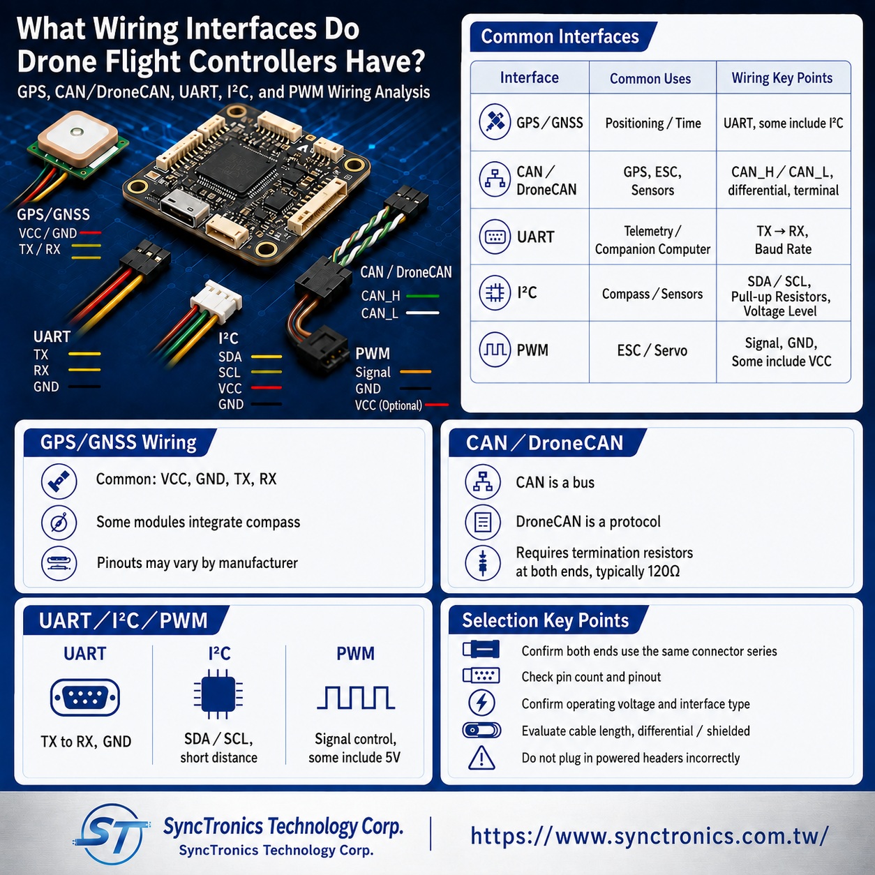
What Are the Most Common Drone Flight Controller Cables?
|
Interface |
Common Applications |
Main Connections |
Key Wiring Considerations |
|
GPS/GNSS |
Positioning and timing information |
UART, sometimes combined with I²C |
TX/RX, power and pin sequence |
|
CAN/DroneCAN |
GPS, ESCs, sensors and power modules |
CAN_H, CAN_L |
Twisted pair, termination and bus topology |
|
UART |
GPS, telemetry and companion computers |
TX, RX, GND |
TX/RX crossover and baud rate |
|
I²C |
Compass, airspeed sensor and other sensors |
SDA, SCL |
Voltage, cable length and pull-up configuration |
|
PWM |
ESCs, servos and actuators |
Signal, GND, sometimes power |
Signal pin and power arrangement |
What Signals Are Commonly Included in GPS Cables?
Traditional GPS/GNSS modules commonly exchange positioning data with the flight controller through UART, so a basic GPS harness often includes power, ground, TX and RX.
Some GPS modules also integrate an electronic compass. In this case, the same cable assembly may carry both UART and I²C signals.
For example, in some Pixhawk-standard GPS interfaces, GPS positioning data is transmitted through UART while compass information is transmitted through I²C. Certain complete GPS ports may also include functions for a safety switch, buzzer or LED.
Therefore, even if two GPS modules use connectors that look identical, their pin assignments may not be the same.
This is particularly important when working with flight controllers from different brands or non-Pixhawk-standard systems. The pinout of both the flight controller and GPS module should always be checked before wiring.
What Is the Difference Between CAN and DroneCAN?
CAN stands for Controller Area Network and refers to the underlying differential communication bus.
DroneCAN is a UAV communication protocol that operates over CAN and allows the flight controller to exchange data with devices such as:
- GPS modules
- Electronic speed controllers
- Sensors
- Power modules
- Other DroneCAN-compatible peripherals
In simple terms:
CAN is the physical communication bus, while DroneCAN is a higher-level communication protocol that runs over CAN.
They should not be treated as two completely different cable types.
Why Are CAN Wires Usually Twisted?
CAN uses two differential signal conductors:
- CAN_H
- CAN_L
Twisting these two conductors together helps ensure that external electromagnetic interference affects both wires in a similar way, improving common-mode noise rejection at the receiver.
This is particularly useful inside drones because motors, electronic speed controllers and high-current power cables can generate significant electromagnetic noise.
CAN wiring should therefore avoid running closely and in parallel with high-current conductors over long distances whenever possible.
CAN bus systems also require proper termination. In many implementations, 120-ohm termination resistors are placed at both ends of the main bus.
The system is generally arranged as a bus rather than connecting every CAN peripheral individually back to the flight controller.
Pixhawk-standard CAN devices commonly use 4-pin JST-GH connectors, but other connector systems may also be used.
How Should UART Cables Be Wired?
UART is one of the most common point-to-point serial communication interfaces used in drones.
Typical UART applications include:
- GPS
- Telemetry
- MAVLink devices
- Companion computers
- Certain ESCs
- Serial sensors
A basic UART connection usually includes:
- TX
- RX
- GND
Some interfaces may also include VCC, CTS and RTS.
The most common wiring principle is:
Flight Controller TX → Device RX
Flight Controller RX → Device TX
In other words, the transmitting pin on one device connects to the receiving pin on the other.
The baud rate, signal voltage and configured port function must also be verified.
Flight controllers may allow ports such as GPS1, TELEM1 or TELEM2 to be reassigned through software, so plugging a device into a port labeled “TELEM” does not automatically guarantee compatibility.
The communication protocol and port configuration must still match.
What Devices Commonly Use I²C Cables?
I²C typically uses two primary signal lines:
- SDA: Serial Data
- SCL: Serial Clock
These are normally accompanied by power and ground.
Common I²C devices in drones include:
- Compasses
- Airspeed sensors
- Distance sensors
- Other low-speed sensor modules
One advantage of I²C is that multiple devices can share the same SDA and SCL lines, which allows the use of I²C splitters in some systems.
However, I²C was originally designed for relatively short communication distances. Excessive cable length, capacitance or electrical interference may cause unstable communication.
Signal voltage must also be checked.
Some I²C devices may use different logic levels from the flight controller interface. A level converter may therefore be required in certain combinations.
What Is PWM Wiring Used for?
PWM is a common control signal used for:
- ESCs
- Servos
- Actuators
- Certain peripheral devices
Traditional PWM ESC or servo wiring often includes:
- PWM Signal
- GND
- Sometimes 5V power
Whether the 5V line is required depends on the ESC, servo and flight controller output rail design.
Modern flight controllers may also support other ESC control methods, including DShot and DroneCAN, so not every current UAV relies exclusively on PWM.
Although PWM harnesses are relatively simple, incorrect wiring of the signal, ground or power pins can still prevent operation or damage connected equipment.
Can Two JST-GH Connectors Always Be Connected Directly?
No.
JST-GH identifies a connector series, not a communication protocol.
For example, GPS, CAN and telemetry ports on a flight controller may all use JST-GH connectors, but they can have different pin counts and completely different pin assignments.
Even if two devices use JST-GH connectors with the same number of positions, different pinouts may result in:
- Reversed power and ground
- Incorrect TX and RX connections
- Swapped CAN_H and CAN_L
- Incompatible supply voltages
Flight controller harnesses should therefore be matched according to the complete pinout, not connector appearance alone.
Should All Flight Controller Signal Cables Be Shielded?
Not necessarily.
Shielding can help reduce electromagnetic interference, but it also increases cable weight, diameter and grounding complexity.
For differential signals such as CAN, correct twisted-pair construction and bus topology are usually the first priorities.
UART and I²C may require shielding depending on cable length, signal speed and the actual interference environment.
Using thick shielded cable for every signal line can add unnecessary weight to a drone.
The shielding strategy should therefore be based on the sensitivity and operating environment of each interface.
What Information Should Be Confirmed When Selecting a Flight Controller Harness?
When designing or requesting a custom harness, it is helpful to provide:
- Flight controller brand and complete model number
- Peripheral device brand and model number
- Complete connector series
- Pin count
- Pinout
- Operating voltage
- UART, CAN, I²C or PWM interface type
- Cable length
- Wire gauge
- Twisted-pair requirements
- Shielding requirements
- Locking and polarization requirements
- Vibration and environmental conditions
Providing the original pinout drawings for both ends can significantly reduce the risk of wiring errors.
Common Wiring Mistakes
Treating JST-GH as a communication standard
JST-GH is only a connector series. CAN, UART and GPS interfaces may all use it.
Connecting UART TX directly to TX
UART normally requires TX-to-RX and RX-to-TX connections.
Checking CAN_H and CAN_L but ignoring termination
Bus topology and 120-ohm termination are also important for reliable CAN communication.
Checking only the I²C pin count but not the signal voltage
Different devices may operate at different logic levels.
Wiring only according to wire color
Wire color is not a universal pinout standard. The manufacturer’s documentation should always be used as the primary reference.
Conclusion
Drone flight controller cables may include GPS, CAN/DroneCAN, UART, I²C and PWM interfaces. These names describe different communication or control methods, not simply different connector types.
GPS may combine UART and I²C signals. DroneCAN operates on a CAN bus. UART is commonly used for point-to-point TX/RX communication. I²C is often used for short-distance sensor connections, while PWM remains common for ESC and servo control.
The key to flight controller harness design is not simply finding a cable that can be physically plugged in.
The connector, pinout, signal voltage, communication interface, cable construction and operating environment on both ends must all be compatible.
SyncTronics Solutions
SyncTronics Technology provides integrated support for drone flight controller harnesses, GPS cables, CAN/DroneCAN harnesses, UART signal cables, I²C sensor harnesses and PWM control cables.
Based on flight controller and peripheral pinouts, cable length, wire gauge, twisted-pair requirements, shielding, locking and polarization needs, we can assist customers with specification verification and suitable interconnect configurations.
For special wiring sequences, interface conversion between different flight controller brands and GPS modules, ESCs, sensors, telemetry equipment and other peripherals, as well as New Product Introduction (NPI) and OEM/ODM projects, SyncTronics can support the evaluation of connectors, terminals, wires and harness configurations to reduce development risks related to incorrect pin assignments, signal interference and interface incompatibility.
Need Wire Harnesses, Connectors, Electromechanical Components, or Custom Solutions? Contact Us Today
Whether you are looking for connectors, cables, wire harness assemblies, electromechanical components, or complete electronic interconnect solutions, SyncTronics provides professional technical support and engineering evaluation for product selection, specification verification, New Product Introduction (NPI), OEM/ODM customization, as well as high-speed transmission, high-reliability, and other specialized application requirements.
We welcome you to visit our Contact Us page and share your project requirements and contact information. Our team is committed to responding quickly and professionally, evaluating the most suitable products and electronic interconnect solutions based on your product specifications, application requirements, and project objectives. We also provide technical recommendations and customized engineering support to help shorten product selection and development time, reduce project risks, and accelerate your path to mass production. We look forward to the opportunity to work with you and provide reliable technical support and practical solutions for every stage of your project.
Related Articles
How to Select Drone Connectors and Wire Harnesses | SyncTronics Technology
Drone Connectors: XT30, XT60, JST-GH and DF13 | SyncTronics Technology
What Is Connector Pin Count? Complete Guide | SyncTronics Technology
Disclaimer and Technical Exchange Statement
This content is compiled based on publicly available information and industry experience, intended solely for reference during technical exchanges. It does not constitute any commercial, technical, or legal advice or basis.
The specifications, materials, manufacturing processes, application methods, and related information described herein may vary due to differing design conditions, environmental factors, or usage scenarios. No guarantees are made regarding the completeness, correctness, or suitability of such content.
Readers should verify the suitability with the responsible design or technical personnel based on actual application scenarios, and independently assess all associated risks.Frequently Asked Questions (FAQ)
- What is Connector Knowledge
- Wire Related issues
- Materials-Related
- Regulatory Issues
- Electronic issues
- What Is the Relationship Between Electronics and Connecting Cables?
- What Is USB PD 3.1? How 240W USB-C Charging Works
- Drone Wire EMI: Power, Signal & Shielding
- What Are Drone Flight Controller Cables? GPS, CAN, UART, I²C and PWM Wiring Guide
- What Is High-Speed Signal Integrity (Signal Integrity, SI)?
- What Is RFI (Radio Frequency Interference)? How Is It Different from EMI?
- Why Are High-Speed Signals More Susceptible to EMI?
- What Is Crosstalk? Causes, Effects, and How to Reduce It
- What Is a Shielded Cable? Why Does It Reduce Electromagnetic Interference?
- What Is Grounding? Why Is It Important for Reducing EMI?
- What Is Signal Integrity? A Complete Guide to High-Speed Signal Transmission
- What Is EMI (Electromagnetic Interference)? How Does It Affect Electronic Products?
- What Is a Ferrite Core? How Does It Suppress EMI?
- How Does Cable Design Reduce EMI? A Complete Guide to EMI Shielding
- How to Reduce EMI and RFI? A Complete Guide to Electromagnetic Interference Mitigation
- Manufacturing Technology
- Testing & Verification
- Quality Management
- History & Evolution