
What Does Connector Pin Count Mean?
What Is Connector Pin Count? Contacts, Positions and Selection Guide
A connector’s pin count generally refers to the number of conductive contacts or electrical circuit positions available within the connector.
For example, a 2-pin connector usually provides two contact positions, while an 8-pin connector provides eight positions that may be assigned to power, ground, control signals or data transmission.
Depending on the connector supplier, product specifications may use terms such as Pin Count, Number of Positions, Number of Contacts, Circuit Count or Number of Circuits. These terms are often related, but their exact definitions may vary between connector series. The manufacturer’s drawing and technical datasheet should therefore remain the primary reference.
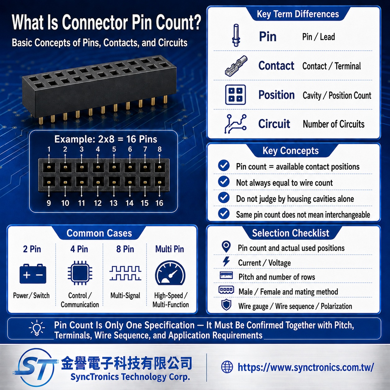
What Is the Difference Between Pin, Contact, Position and Circuit?
These terms are often used interchangeably, but they do not always mean exactly the same thing.
|
Term |
Common Meaning |
Typical Definition |
|
Pin |
Male pin or terminal |
A protruding conductive contact, commonly found on a plug or board-mounted connector |
|
Contact |
Electrical contact or terminal |
A general term covering male pins, female receptacles and other conductive contact parts |
|
Position |
Contact position or cavity |
A location in the connector housing where a terminal may be installed |
|
Circuit |
Electrical circuit position |
An independent electrical connection path through the connector |
In many standard connectors, the number of positions, contacts and circuits may be identical. However, some connector housings include unused cavities, unpopulated terminal positions or several different contact types.
For this reason, the number of visible holes in a connector housing does not always represent the number of installed contacts.
A common example is a connector described as 6P4C, which has six physical positions but only four conductive contacts. This is why engineers and purchasing teams should verify the actual contact configuration and wiring diagram rather than relying only on the housing appearance.
Is Pin Count the Same as Wire Count?
Not always.
In wire-to-wire and wire-to-board connector assemblies, one installed contact commonly corresponds to one conductor. As a result, the number of pins may often be close to the number of wires.
However, there are several common exceptions:
- Some positions may not contain terminals
- Certain pins may be reserved or unused
- Several contacts may share the same power or ground function
- The connector may be mounted directly onto a printed circuit board
- Shielding tabs or mechanical mounting posts may not be included in the standard pin count
- Hybrid connectors may combine power, signal, coaxial or optical contacts
When requesting a wire harness quotation, it is therefore important to provide not only the connector pin count, but also the actual wire count, wire gauge, pin functions and wiring configuration.
Does a Higher Pin Count Mean Better Performance?
A higher pin count normally allows more electrical connections, but it does not automatically mean that the connector supports higher speed, greater current or better performance.
The connector’s actual electrical and mechanical capabilities also depend on:
- Contact dimensions and conductor cross-section
- Rated current and rated voltage
- Contact pitch
- Insulation material
- Contact resistance
- Contact plating material and thickness
- Signal and ground allocation
- Shielding structure
- Operating environment
- Mating cycle requirements
For example, a high-current power connector may contain only two or three large contacts, while a high-speed data connector may contain dozens of small signal and ground contacts.
Pin count is therefore only one part of the connector specification and should not be used alone to evaluate performance.
From Which Side Should Pin Numbers Be Viewed?
Connector pin numbering must be confirmed according to the viewing direction shown in the manufacturer’s drawing.
A technical drawing may show the connector from several different perspectives:
- Mating face
- Wire-entry side
- Solder side
- Printed circuit board side
- Plug side
- Receptacle side
Male and female connectors must align after mating, which means their pin layouts may appear mirrored when viewed from the front.
If the drawing orientation is misunderstood, the result may be reversed wiring, incorrect polarity or misplaced signal connections.
Before wiring or assembly, always verify the pin number, viewing direction, connector gender and wiring table together. Connector appearance alone should not be used to determine the pin sequence.
Can Connectors With the Same Pin Count Be Interchanged?
Pin count alone is not sufficient to determine interchangeability.
Two connectors may both be described as 4-pin, 8-pin or 20-pin products, but they may still be mechanically or electrically incompatible because of differences in:
- Connector series
- Contact pitch
- Number of rows
- Contact arrangement
- Housing dimensions
- Plug or receptacle configuration
- Polarization features
- Latching or locking structure
- Terminal size
- Applicable wire gauge
- Rated current and voltage
- Mounting method
- Pin assignment
- Wiring sequence
For example, two 4-pin connectors may look similar but belong to completely different product families with different pitches, terminals and locking directions.
Even when two connectors can be physically inserted, an incorrect match may lead to poor contact, terminal damage, overheating or equipment failure.
What Information Should Be Confirmed When Selecting Pin Count?
Connector selection should begin by identifying every electrical function that must pass through the interface, including power, ground, control, communication and any reserved positions.
The total number of required contacts can then be determined.
For product selection or quotation, it is helpful to provide:
- Required pin count
- Actual number of used positions
- Function of each pin
- Rated current
- Operating voltage
- Wire count
- Wire gauge
- Contact pitch
- Number of rows
- Plug and receptacle configuration
- Wire-to-wire, wire-to-board or board-to-board structure
- Crimp, solder, DIP or SMT termination
- Polarization, latch, waterproofing or shielding requirements
- Original manufacturer part number
- Technical drawing or product photograph
The more complete the information, the lower the risk of selecting the wrong housing, terminal, wire size or pin configuration.
Common Misunderstandings
Does the number of holes always equal the pin count?
Not necessarily. Some cavities may be empty, and other openings may serve mechanical positioning or locking functions. Always refer to the product specification.
Are mounting posts and shielding tabs included in the pin count?
Standard pin count usually refers to the main electrical contacts. Whether shielding tabs, grounding tabs or mechanical mounting posts are included depends on the supplier’s product definition.
Do connectors with the same pin count have the same wiring sequence?
No. The same contact count does not guarantee the same pin assignment, polarity, signal definition or wiring sequence.
Can unused positions be left without terminals?
Some connector series allow unused cavities, but waterproof connectors may require sealing plugs or specific assembly procedures. Terminal retention, sealing performance and supplier requirements should always be confirmed.
Conclusion
Connector pin count generally represents the number of available conductive contacts or electrical positions, but it does not necessarily equal the number of installed terminals, wires or signals.
Connector selection must also consider pitch, contact arrangement, connector gender, terminal specifications, pin numbering, current, voltage, wire gauge and polarization features.
Connectors with the same pin count are not automatically interchangeable. Manufacturer part numbers, technical drawings and actual application requirements should always be verified before final selection.
Need Wire Harnesses, Connectors, Electromechanical Components, or Custom Solutions? Contact Us Today
Whether you are looking for connectors, cables, wire harness assemblies, electromechanical components, or complete electronic interconnect solutions, SyncTronics provides professional technical support and engineering evaluation for product selection, specification verification, New Product Introduction (NPI), OEM/ODM customization, as well as high-speed transmission, high-reliability, and other specialized application requirements.
We welcome you to visit our Contact Us page and share your project requirements and contact information. Our team is committed to responding quickly and professionally, evaluating the most suitable products and electronic interconnect solutions based on your product specifications, application requirements, and project objectives. We also provide technical recommendations and customized engineering support to help shorten product selection and development time, reduce project risks, and accelerate your path to mass production. We look forward to the opportunity to work with you and provide reliable technical support and practical solutions for every stage of your project.
Related Articles:
What Is Connector Pitch? Complete Guide | SyncTronics Technology
Terminal vs Connector vs Header: Differences Explained | SyncTronics Technology
What Is Contact Resistance? Complete Guide | SyncTronics Technology
What Is Insertion & Extraction Force? Guide | SyncTronics Technology
What Is Retention Force? Complete Guide | SyncTronics Technology
Disclaimer and Technical Exchange Statement
This content is compiled based on publicly
available information and industry experience, intended solely for reference
during technical exchanges. It does not constitute any commercial, technical,
or legal advice or basis.
The specifications, materials, manufacturing processes, application methods,
and related information described herein may vary due to differing design
conditions, environmental factors, or usage scenarios. No guarantees are made
regarding the completeness, correctness, or suitability of such content.
Readers should verify the suitability with the responsible design or technical
personnel based on actual application scenarios, and independently assess all
associated risks.
Frequently Asked Questions (FAQ)
- What is Connector Knowledge
- What Is a Connector?
- Euro-Style vs. Barrier Terminal Blocks
- Ring vs. Fork Terminals: Differences
- What Is an IDC Connector?
- Box Header vs. Ejector Header: Latching, Ejection, and When to Use Each
- What Is a Box Header?
- 6 Common Connector Selection Mistakes and How to Avoid Them
- How to Select a USB Type-C Connector: Mating Cycles, Current Rating & PCB Mounting
- How to Select Industrial Automation Connectors: Locking, Vibration Resistance & Retention
- How to Select Energy Storage Connectors: Current Rating, Contact Resistance & Keying
- Why Do High-Current Connectors Overheat? Contact Resistance, Terminals & Crimp Quality
- What Is a Terminal Block? Types, Structure & Selection
- Wire-to-Board vs. Board-to-Board Connectors: Structure and Selection
- How to Select Drone Connectors and Wire Harnesses: Power, Flight Controller, GPS and Signal Connections
- What Connectors Are Commonly Used in Drones? XT30, XT60, JST-GH, and DF13 Explained
- How to Select Drone Battery Connectors: XT30, XT60 and XT90
- Why Do Drone Connectors Become Loose? Vibration Resistance, Polarization and Retention Design
- RJ45 Connector Structure and Applications Guide
- What Is Connector Pitch?
- What Does Connector Pin Count Mean?
- What Is the Difference Between a Terminal, a Connector, and a Coupling?
- What Is Contact Resistance, and What Does It Affect?
- What Is Connector Insertion and Withdrawal Force?
- What Is Retention Force?
- What Is Poka-Yoke (Error-Proofing) Design?
- What Is Gold Plating Thickness? Why Does It Affect Connector Lifespan?
- What Is the Difference Between SMT Connectors and DIP Connectors?
- Wire Related issues
- Materials-Related
- Regulatory Issues
- Electronic issues
- Manufacturing Technology
- Testing & Verification
- Quality Management
- History & Evolution