
What Is the Difference Between SMT Connectors and DIP Connectors?
The main difference between SMT (Surface Mount Technology) connectors and DIP (Dual In-line Package / Through-Hole) connectors is how they are mounted onto a printed circuit board (PCB). SMT connectors are soldered directly onto the PCB surface, while DIP connectors use pins that pass through drilled holes in the PCB before being soldered. Each type offers distinct advantages depending on the application.
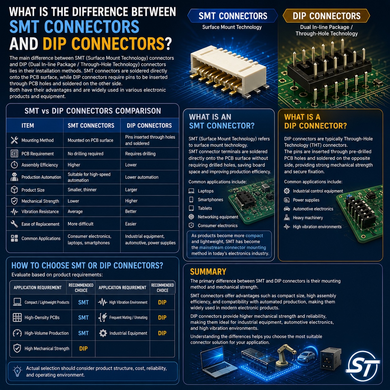
SMT vs DIP Connector Comparison
|
Feature |
SMT Connector |
DIP Connector |
|
Mounting Method |
Surface-mounted on PCB |
Through-hole mounted |
|
PCB Requirement |
No drilling required |
PCB holes required |
|
Assembly Efficiency |
Higher |
Lower |
|
Automation Compatibility |
Excellent |
Moderate |
|
Product Size |
Smaller and more compact |
Larger |
|
Mechanical Strength |
Lower |
Higher |
|
Vibration Resistance |
Standard |
Better |
|
Maintenance & Replacement |
More difficult |
Easier |
|
Typical Applications |
Consumer electronics, laptops, smartphones |
Industrial equipment, automotive electronics, power systems |
What Is an SMT Connector?
SMT stands for Surface Mount Technology.
An SMT connector is mounted directly onto the surface of a PCB without requiring holes. This allows manufacturers to save board space, increase component density, and improve production efficiency.
Common applications include:
- Laptops
- Smartphones
- Tablets
- Networking equipment
- Consumer electronics
As electronic devices continue to become smaller and thinner, SMT connectors have become one of the most widely used connector types in modern electronics manufacturing.
What Is a DIP Connector?
A DIP connector is typically installed using Through-Hole Technology (THT).
Its pins are inserted through pre-drilled PCB holes and soldered on the opposite side of the board. This design provides stronger mechanical retention and improved durability.
Common applications include:
- Industrial control systems
- Power supplies
- Automotive electronics
- Heavy-duty equipment
- High-vibration environments
For applications that require frequent mating cycles or greater mechanical strength, DIP connectors often remain the preferred choice.
How Do You Choose Between SMT and DIP Connectors?
The selection usually depends on product requirements.
|
Application Requirement |
Recommended Type |
|
Compact product design |
SMT |
|
High-density PCB layout |
SMT |
|
High-volume automated production |
SMT |
|
High mechanical strength |
DIP |
|
High-vibration environments |
DIP |
|
Frequent insertion and removal |
DIP |
|
Industrial equipment |
DIP |
Factors such as product design, cost, reliability, and operating environment should all be considered when selecting a connector type.
Summary
The key difference between SMT and DIP connectors lies in their mounting methods and mechanical characteristics. SMT connectors offer compact size, efficient assembly, and compatibility with automated manufacturing, making them ideal for modern electronic devices. DIP connectors provide stronger mechanical support and durability, making them well suited for industrial, automotive, and high-reliability applications. Understanding these differences can help engineers and buyers select the most suitable connector solution for their products.
Need Wire Harnesses, Connectors, Electromechanical Components, or Custom Solutions? Contact Us Today
Whether you are looking for connectors, cables, wire harness assemblies, electromechanical components, or complete electronic interconnect solutions, SyncTronics provides professional technical support and engineering evaluation for product selection, specification verification, New Product Introduction (NPI), OEM/ODM customization, as well as high-speed transmission, high-reliability, and other specialized application requirements.
We welcome you to visit our Contact Us page and share your project requirements and contact information. Our team is committed to responding quickly and professionally, evaluating the most suitable products and electronic interconnect solutions based on your product specifications, application requirements, and project objectives. We also provide technical recommendations and customized engineering support to help shorten product selection and development time, reduce project risks, and accelerate your path to mass production. We look forward to the opportunity to work with you and provide reliable technical support and practical solutions for every stage of your project.
Related Articles:
What Is Contact Resistance? Complete Guide | SyncTronics Technology
What Is Insertion & Extraction Force? Guide | SyncTronics Technology
What Is Retention Force? Complete Guide | SyncTronics Technology
What Is Connector Pitch? Complete Guide | SyncTronics Technology
Terminal vs Connector vs Header: Differences Explained | SyncTronics Technology
Disclaimer and Technical Exchange
Statement
This content is compiled based on publicly
available information and industry experience, intended solely for reference
during technical exchanges. It does not constitute any commercial, technical,
or legal advice or basis.
The specifications, materials, manufacturing processes, application methods,
and related information described herein may vary due to differing design
conditions, environmental factors, or usage scenarios. No guarantees are made
regarding the completeness, correctness, or suitability of such content.
Readers should verify the suitability with the responsible design or technical
personnel based on actual application scenarios, and independently assess all
associated risks.
Frequently Asked Questions (FAQ)
- What is Connector Knowledge
- What Is a Connector?
- Euro-Style vs. Barrier Terminal Blocks
- Ring vs. Fork Terminals: Differences
- What Is an IDC Connector?
- Box Header vs. Ejector Header: Latching, Ejection, and When to Use Each
- What Is a Box Header?
- 6 Common Connector Selection Mistakes and How to Avoid Them
- How to Select a USB Type-C Connector: Mating Cycles, Current Rating & PCB Mounting
- How to Select Industrial Automation Connectors: Locking, Vibration Resistance & Retention
- How to Select Energy Storage Connectors: Current Rating, Contact Resistance & Keying
- Why Do High-Current Connectors Overheat? Contact Resistance, Terminals & Crimp Quality
- What Is a Terminal Block? Types, Structure & Selection
- Wire-to-Board vs. Board-to-Board Connectors: Structure and Selection
- How to Select Drone Connectors and Wire Harnesses: Power, Flight Controller, GPS and Signal Connections
- What Connectors Are Commonly Used in Drones? XT30, XT60, JST-GH, and DF13 Explained
- How to Select Drone Battery Connectors: XT30, XT60 and XT90
- Why Do Drone Connectors Become Loose? Vibration Resistance, Polarization and Retention Design
- RJ45 Connector Structure and Applications Guide
- What Is Connector Pitch?
- What Does Connector Pin Count Mean?
- What Is the Difference Between a Terminal, a Connector, and a Coupling?
- What Is Contact Resistance, and What Does It Affect?
- What Is Connector Insertion and Withdrawal Force?
- What Is Retention Force?
- What Is Poka-Yoke (Error-Proofing) Design?
- What Is Gold Plating Thickness? Why Does It Affect Connector Lifespan?
- What Is the Difference Between SMT Connectors and DIP Connectors?
- Wire Related issues
- Materials-Related
- Regulatory Issues
- Electronic issues
- Manufacturing Technology
- Testing & Verification
- Quality Management
- History & Evolution