
What Is a Differential Signal Cable?
What Is a Differential Signal Cable?
A differential signal cable uses two matched conductors to transmit a signal as a pair. These conductors are typically identified as Positive (P / +) and Negative (N / −). Instead of evaluating the voltage on either conductor independently, the receiver determines the transmitted data by measuring the voltage difference between the two conductors, known as the differential voltage.
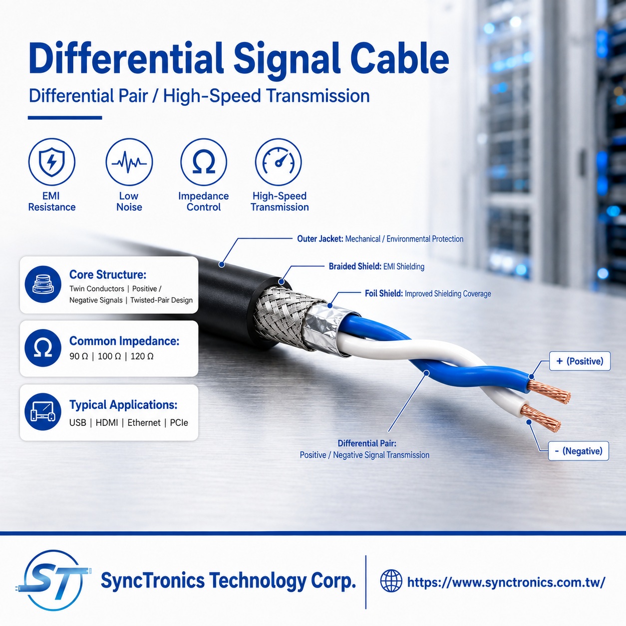
A simple way to remember the concept is:
Two conductors, one voltage difference, shared noise, better noise rejection.
Differential signaling provides strong noise immunity and is widely used in high-speed and high-reliability interfaces such as Ethernet, USB, HDMI, PCI Express, LVDS, and CAN.
How Does Differential Signaling Work?
A simplified voltage example makes the concept easier to understand.
Assume that, at a given moment, the two signal conductors carry:
P line: +0.5V
N line: -0.5V
The receiver evaluates the difference:
+0.5V − (-0.5V) = 1.0V
Now assume external electromagnetic interference adds +0.2V to both conductors:
P line becomes +0.7V
N line becomes -0.3V
The voltage difference is still:
+0.7V − (-0.3V) = 1.0V
When external noise affects both conductors by approximately the same amount, subtracting one signal from the other helps reject that common disturbance. Noise that appears similarly on both conductors is commonly referred to as common-mode noise.
Actual signaling voltages and receiver thresholds vary by interface standard, but the fundamental principle remains the same:
The receiver is primarily interested in the voltage difference between the two conductors rather than the voltage of a single conductor relative to ground.
Why Are Differential Pairs Often Twisted?
For differential signaling to reject external interference effectively, both conductors should experience a similar electromagnetic environment.
This is why many differential pairs use a twisted-pair structure.
By continuously twisting the two conductors together, each conductor alternates its physical position relative to nearby interference sources. This helps equalize the electromagnetic effects on both conductors and improves pair balance, noise immunity, and EMI performance.
However, two concepts should not be confused:
Differential signaling does not automatically mean twisted pair, and a twisted pair does not necessarily carry a differential signal.
“Differential” describes the signaling method, while “twisted pair” describes the physical cable structure. They are frequently used together, but they are not the same thing.
Why Is Differential Signaling Common in High-Speed Transmission?
As data rates increase, signal transition times become faster, making cables, connectors, PCBs, and the surrounding electromagnetic environment increasingly important to signal quality.
Differential transmission offers several advantages:
- Improved rejection of common-mode noise
- Reduced sensitivity to external electromagnetic interference
- Better signal integrity
- Suitability for high-frequency and high-speed data transmission
- Reduced unwanted radiation and mode conversion when the channel is properly balanced
For these reasons, differential signaling is widely used in high-speed networking, servers, data centers, industrial communications, and digital interfaces.
What Is Differential Impedance?
A differential signal cable requires more than simply two conductors. One of the most important electrical characteristics is differential impedance.
At high data rates, signals behave as electromagnetic waves propagating through a transmission line. Significant impedance discontinuities between the cable, connector, PCB, and termination can cause signal reflections, which may lead to waveform distortion, jitter, and degraded signal quality.
Differential impedance can be affected by factors such as:
- Conductor size
- Spacing between the two conductors
- Insulation material
- Twist pitch
- Shielding structure
- Connector design
- Termination and assembly consistency
There is no single differential impedance value that applies to every interface.
For example, LVDS commonly uses transmission lines near 100Ω differential impedance. Ethernet balanced cabling commonly uses a nominal impedance around 100Ω. High-speed CAN networks typically use termination matched to approximately 120Ω cable impedance. USB requirements vary by generation and channel definition; USB4, for example, includes differential impedance requirements around an 85Ω reference.
The actual impedance requirement should always be determined according to the applicable interface specification.
Why Does Pair Length Matching Matter?
The P and N conductors of a differential pair should experience similar transmission conditions.
If one conductor is significantly longer than the other, the two signals may arrive at the receiver at slightly different times. This timing difference is called:
Intra-Pair Skew
As transmission speeds increase, the allowable timing difference generally becomes smaller.
For this reason, high-speed differential cable design and assembly may need to control:
- P / N conductor length matching
- Twist consistency
- Connector termination length
- Strip and untwist length
- Shielding structure
- Impedance continuity through the cable and connector
This is why verifying electrical continuity alone is not sufficient for many high-speed differential interconnects.
Where Are Differential Signal Cables Used?
Differential signaling is widely used in high-speed data transmission and industrial communications, including:
USB
HDMI
DisplayPort
Ethernet
PCI Express (PCIe)
SATA
LVDS
CAN Bus
RS-485
AI servers and data center equipment
Networking equipment
Industrial automation systems
Each interface has different requirements for impedance, cable length, data rate, connector type, shielding, and overall channel design.
Therefore, cables should not be considered interchangeable simply because they all use differential signaling.
Differential vs. Single-Ended Signaling
|
Comparison |
Differential Signaling |
Single-Ended Signaling |
|
Signal Detection |
Measures the voltage difference between two conductors |
Measures signal voltage relative to a reference ground |
|
Signal Conductors |
Matched signal pair |
Signal conductor with reference ground |
|
Common-Mode Noise Rejection |
Generally better |
More sensitive to common external interference |
|
High-Speed Applications |
Widely used |
Depends on interface and data rate |
|
Key Design Factors |
Differential impedance, balance, skew, shielding |
Impedance, grounding, return path |
Differential signaling is not inherently the best choice for every application. The appropriate signaling architecture depends on the interface standard, transmission distance, data rate, cost, and overall system design.
How Do You Select a Differential Signal Cable?
When selecting a cable for a differential interface, several factors should be confirmed first:
- Equipment or interface specification
- Required differential impedance
- Data rate and transmission distance
- Connector and pinout definition
- Twisted-pair requirements
- Foil and/or braid shielding requirements
- EMI environment
- P / N pair length and assembly consistency
- Impedance or signal-integrity verification requirements
For high-speed applications in particular, cables should not be considered equivalent simply because they use the same AWG size or because the connectors physically fit.
Application Solutions
The actual structure of a differential signal cable should be based on customer drawings, equipment specifications, interface definitions, or original equipment manufacturer documentation.
SyncTronics supports the evaluation of connectors, terminals, wire and cable specifications, cable length, twisted-pair construction, shielding, and wire harness or cable assembly requirements based on customer-defined specifications.
These interconnect solutions can support applications including high-speed transmission, networking equipment, AI servers, industrial automation, and other electronic systems.
Conclusion
The key principle of differential signaling is simple:
Two matched conductors carry the signal together, and the receiver determines the data by measuring the voltage difference between them.
When external interference affects both conductors similarly, differential reception can help reject common-mode noise. Combined with appropriate twisted-pair construction, impedance control, pair balance, shielding, and termination design, differential signaling can provide reliable performance in high-speed applications.
The performance of a differential cable therefore depends on much more than simply having “two wires.” The entire transmission path—including impedance, cable geometry, pair balance, connectors, cable length, and assembly consistency—can affect signal integrity.
Need Wire Harnesses, Connectors, Electromechanical Components, or Custom Solutions? Contact Us Today
Whether you are looking for connectors,
cables, wire harness assemblies, electromechanical components, or complete
electronic interconnect solutions, SyncTronics provides professional technical
support and engineering evaluation for product selection, specification
verification, New Product Introduction (NPI), OEM/ODM customization, as well as
high-speed transmission, high-reliability, and other specialized application
requirements.
We welcome you to visit our Contact Us page and
share your project requirements and contact information. Our team is committed
to responding quickly and professionally, evaluating the most suitable
products and electronic interconnect solutions based on your product
specifications, application requirements, and project objectives. We also
provide technical recommendations and customized engineering support to help
shorten product selection and development time, reduce project risks, and
accelerate your path to mass production. We look forward to the opportunity to
work with you and provide reliable technical support and practical solutions
for every stage of your project.
Related Articles:
What Is Cable Assembly? Complete Guide | SyncTronics Technology
What Are UL-Rated Wires? UL Wire Certification & Standards Explained | SyncTronics Technology
What Is AWG Wire Gauge? Complete Guide | SyncTronics Technology
Disclaimer and Technical Exchange Statement
This content is compiled based on publicly
available information and industry experience, intended solely for reference
during technical exchanges. It does not constitute any commercial, technical,
or legal advice or basis.
The specifications, materials, manufacturing processes, application methods,
and related information described herein may vary due to differing design
conditions, environmental factors, or usage scenarios. No guarantees are made
regarding the completeness, correctness, or suitability of such content.
Readers should verify the suitability with the responsible design or technical
personnel based on actual application scenarios, and independently assess all
associated risks.
Frequently Asked Questions (FAQ)
- What is Connector Knowledge
- Wire Related issues
- What Is Wire Harness Assembly? Complete Guide to the Process, Applications, and Benefits
- 60W vs. 100W vs. 140W vs. 240W USB-C Cables: What's the Difference?
- Are All USB-C Cables the Same?
- Solar vs. Energy Storage Cables: Weather Resistance, Voltage & Selection Guide
- What Is a BMS Wire Harness? Cell Voltage, Temperature Sensing & Balancing Explained
- How to Select Energy Storage Power Wire Harnesses: Current, Voltage, Temperature Rise & Flame Retardancy
- What Is Silicone Wire? High-Temperature Properties, Structure & Selection
- How to Choose AWG Wire Size for Drone Power Cables
- How to Select Drone Wires: Lightweight Design, Flexibility, Heat Resistance and Waterproofing
- What Is a High-Speed Transmission Cable?
- What Is a Twisted Pair Cable? Why Does It Reduce Electromagnetic Interference?
- Industrial Cable Applications Explained: How to Select High Temperature, Waterproof, and High Reliability Cables
- What Are the Steps in Wire Processing? Complete Guide to the Manufacturing Process
- What Are Wire Cutting, Wire Stripping, Crimping, and Assembly?
- What Is a High Temperature Cable?
- What Is an Oil-Resistant and Abrasion-Resistant Cable?
- What Is a Waterproof Cable?
- What Are UL-Rated Wires?
- What Is AWG Wire Gauge? How Do You Choose the Right Wire Size?
- What Is a Controlled Impedance Cable?
- What Is a Differential Signal Cable?
- What Is a High Frequency Cable?
- What Is the Difference Between a Coaxial Cable and a Ribbon Cable?
- Older Network Cable Versions Explained: What Are CAT3, CAT4, and CAT5?
- CAT5e vs CAT6 vs CAT6a vs CAT7 vs CAT8 Complete Guide
- STP vs UTP Ethernet Cables: Understanding Shielded and Unshielded Twisted Pair Differences
- What Are the Differences Between USB, HDMI, D-Sub, and LVDS Cables?
- Materials-Related
- Regulatory Issues
- Electronic issues
- Manufacturing Technology
- Testing & Verification
- Quality Management
- History & Evolution