
How to Select a USB Type-C Connector: Mating Cycles, Current Rating & PCB Mounting
USB Type-C, commonly called USB-C, is a compact reversible connector interface introduced in 2014. It has since become widely used in smartphones, laptops, tablets, industrial equipment, and many other electronic products because the plug can be inserted in either orientation.
Its adoption accelerated further when Apple moved the iPhone 15 series to USB-C in 2023, replacing the proprietary Lightning connector on new iPhones.
However, USB Type-C describes the connector interface—not the USB version, data rate, charging power, or supported features. Two USB-C receptacles may look nearly identical while supporting very different functions, current levels, pin configurations, and PCB mounting structures.
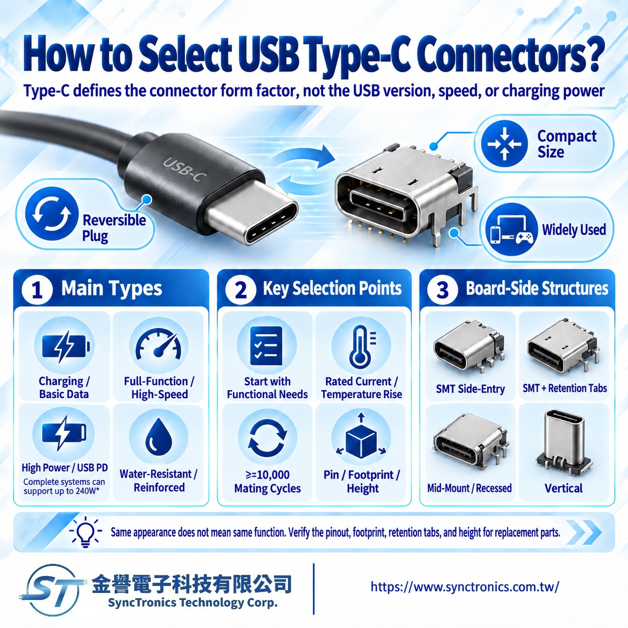
What Are the Main Types of USB Type-C Connectors?
From a practical product-selection perspective, USB-C connectors can be grouped into several common application types.
|
Type |
Typical Application and Selection Focus |
|
Charging / Basic Data |
Charging and USB 2.0 applications; confirm actual pin configuration and current requirements |
|
Full-Featured / High-Speed |
USB 3.x, USB4, high-speed data, or video applications; signal configuration and PCB design become more important |
|
High-Power |
USB Power Delivery applications; connector, cable, PD controller, PCB, and thermal design must work together |
|
Waterproof / Reinforced |
Industrial, outdoor, or high-reliability products; review sealing, IP rating, and mechanical retention |
Instead of starting with the number of pins, the better first question is:
Will this USB-C port be used for charging, basic data, high-speed data, video, or a combination of power and data?
Once the required function is clear, the pin assignment and connector specification can be matched accordingly.
How Much Current Can a USB Type-C Connector Carry?
USB-C is commonly associated with high-power charging, but the connector shape alone does not determine how much current a product can safely carry.
USB Type-C combined with USB Power Delivery can support power levels up to 240 W. However, this is a complete system capability—not a rating provided by the connector alone.
A high-power USB-C design may also depend on:
- Connector current rating
- Contact resistance
- PCB copper and layout
- Thermal performance
- Cable current capability
- E-Marker requirements
- USB PD controller and power architecture
A connector datasheet showing a 5 A rating therefore does not automatically mean the entire device can continuously operate at 5 A.
The complete power path must be evaluated.
Why Do USB-C Mating Cycles Matter?
USB-C is often used as an external interface that may be plugged and unplugged frequently.
The USB Type-C connector system is designed around a minimum durability target of 10,000 mating cycles, which is why many USB-C connectors are specified around this level.
For product selection, the mating-cycle number should not be reviewed by itself. Engineers should also consider whether repeated use affects:
- Contact resistance
- Insertion and withdrawal force
- Contact plating wear
- Metal shell integrity
- Mechanical retention
Actual performance should always be confirmed using the complete manufacturer part number and its specified test conditions.
How Do SMT, Through-Hole, and Mid-Mount USB-C Connectors Differ?
USB-C receptacles can look very similar from the outside while using completely different PCB mounting structures.
|
PCB Structure |
Typical Selection Consideration |
|
SMT / Right-Angle |
Common side-entry design; verify footprint and connector height |
|
SMT + Through-Hole Tabs |
Signal contacts use SMT while shell or mounting tabs pass through the PCB for additional mechanical strength |
|
Mid-Mount |
Part of the connector sits within the PCB, reducing interface height |
|
Vertical |
Mating direction is perpendicular to the PCB; useful for specific mechanical layouts |
For replacement-part evaluation, also compare:
PCB footprint, mounting tabs, locating posts, PCB thickness, connector centerline, and enclosure opening dimensions.
Even when two connectors have the same USB-C interface, a small mechanical difference may prevent direct replacement.
Why Has USB-C Become a Common Charging Interface?
USB-C adoption is driven not only by its reversible design and data capabilities, but also by the move toward interface standardization.
The European Union’s common charger rules were introduced to reduce charging-interface fragmentation across brands, improve charger interoperability, and reduce unnecessary electronic waste.
The requirements began applying to several categories of portable electronic devices, including smartphones, tablets, and digital cameras, on December 28, 2024. Laptops are included from April 28, 2026.
This regulatory direction has helped move USB-C from one available connector option toward a broadly shared charging interface across multiple product categories.
What About Waterproof and High-Speed USB-C Applications?
For high-speed USB-C applications, connector selection is only part of the signal path.
The design may also require careful attention to:
- Differential routing
- Controlled impedance
- Grounding
- Shielding
- PCB transition quality
Replacing a connector with another part that has the same physical interface does not guarantee the same high-speed performance.
For waterproof applications, also review:
- Connector IP rating
- Seal location and structure
- PCB and enclosure integration
- Gasket or sealing design
A connector with an IP rating does not automatically give the finished device the same IP protection level.
Summary
USB Type-C has become one of the most widely used connector interfaces in modern electronics, but one principle is especially important:USB Type-C defines the connector interface. It does not guarantee the same data rate, charging power, or functionality across all USB-C products.
A practical selection sequence is:
Function → Current / Power → Pin Configuration → PCB Mounting → Mechanical Dimensions → Mating Life → Operating Environment
For new designs or alternative-part evaluation, the complete datasheet, PCB footprint, electrical requirements, and system architecture should be reviewed rather than relying on connector appearance alone.
SyncTronics Solutions
As a Taiwan-based electronic interconnect solutions supplier, SyncTronics Technology can support USB Type-C and other board-level connector projects by assisting with functional requirements, pin configuration, current rating, SMT / through-hole mounting, right-angle, vertical and mid-mount structures, PCB footprint, installation height, and waterproofing requirements.
For NPI, OEM/ODM, and alternative-part projects, SyncTronics can also support part-number and datasheet comparisons based on the original connector, available PCB space, and actual product requirements. For USB PD high-power or high-speed applications, the cable, PCB, connector, and complete system design should be evaluated together.
Need Wire Harnesses, Connectors, Electromechanical Components, or Custom Solutions? Contact Us Today
Whether you are looking for connectors, cables, wire harness assemblies, electromechanical components, or complete electronic interconnect solutions, SyncTronics provides professional technical support and engineering evaluation for product selection, specification verification, New Product Introduction (NPI), OEM/ODM customization, as well as high-speed transmission, high-reliability, and other specialized application requirements.
We welcome you to visit our Contact Us page and share your project requirements and contact information. Our team is committed to responding quickly and professionally, evaluating the most suitable products and electronic interconnect solutions based on your product specifications, application requirements, and project objectives. We also provide technical recommendations and customized engineering support to help shorten product selection and development time, reduce project risks, and accelerate your path to mass production. We look forward to the opportunity to work with you and provide reliable technical support and practical solutions for every stage of your project.
Related Articles
USB Type-A, Type-C & Waterproof Connectors | SyncTronics Technology
What Is Contact Resistance? Complete Guide | SyncTronics Technology
What Is Connector Pitch? Complete Guide | SyncTronics Technology
Disclaimer and Technical Exchange Statement
This content is compiled based on publicly available information and industry experience, intended solely for reference during technical exchanges. It does not constitute any commercial, technical, or legal advice or basis.
The specifications, materials, manufacturing processes, application methods, and related information described herein may vary due to differing design conditions, environmental factors, or usage scenarios. No guarantees are made regarding the completeness, correctness, or suitability of such content.
Readers should verify the suitability with the responsible design or technical personnel based on actual application scenarios, and independently assess all associated risks.
Frequently Asked Questions (FAQ)
- What is Connector Knowledge
- What Is a Connector?
- Euro-Style vs. Barrier Terminal Blocks
- Ring vs. Fork Terminals: Differences
- What Is an IDC Connector?
- Box Header vs. Ejector Header: Latching, Ejection, and When to Use Each
- What Is a Box Header?
- 6 Common Connector Selection Mistakes and How to Avoid Them
- How to Select a USB Type-C Connector: Mating Cycles, Current Rating & PCB Mounting
- How to Select Industrial Automation Connectors: Locking, Vibration Resistance & Retention
- How to Select Energy Storage Connectors: Current Rating, Contact Resistance & Keying
- Why Do High-Current Connectors Overheat? Contact Resistance, Terminals & Crimp Quality
- What Is a Terminal Block? Types, Structure & Selection
- Wire-to-Board vs. Board-to-Board Connectors: Structure and Selection
- How to Select Drone Connectors and Wire Harnesses: Power, Flight Controller, GPS and Signal Connections
- What Connectors Are Commonly Used in Drones? XT30, XT60, JST-GH, and DF13 Explained
- How to Select Drone Battery Connectors: XT30, XT60 and XT90
- Why Do Drone Connectors Become Loose? Vibration Resistance, Polarization and Retention Design
- RJ45 Connector Structure and Applications Guide
- What Is Connector Pitch?
- What Does Connector Pin Count Mean?
- What Is the Difference Between a Terminal, a Connector, and a Coupling?
- What Is Contact Resistance, and What Does It Affect?
- What Is Connector Insertion and Withdrawal Force?
- What Is Retention Force?
- What Is Poka-Yoke (Error-Proofing) Design?
- What Is Gold Plating Thickness? Why Does It Affect Connector Lifespan?
- What Is the Difference Between SMT Connectors and DIP Connectors?
- Wire Related issues
- Materials-Related
- Regulatory Issues
- Electronic issues
- Manufacturing Technology
- Testing & Verification
- Quality Management
- History & Evolution