
What Is Injection Molding? Connector Housing Process and Quality Explained
Injection molding is a manufacturing process in which plastic material is heated until it becomes flowable, injected into a mold cavity, held under pressure, cooled, and then removed as a finished part.
For connectors, injection molding is commonly used to produce plastic housings, terminal retainers, insulation structures, keying features, and other mechanical elements. The quality of the molded part affects far more than appearance—it can directly influence terminal positioning, pin spacing, locking features, mating fit, and dimensional stability.
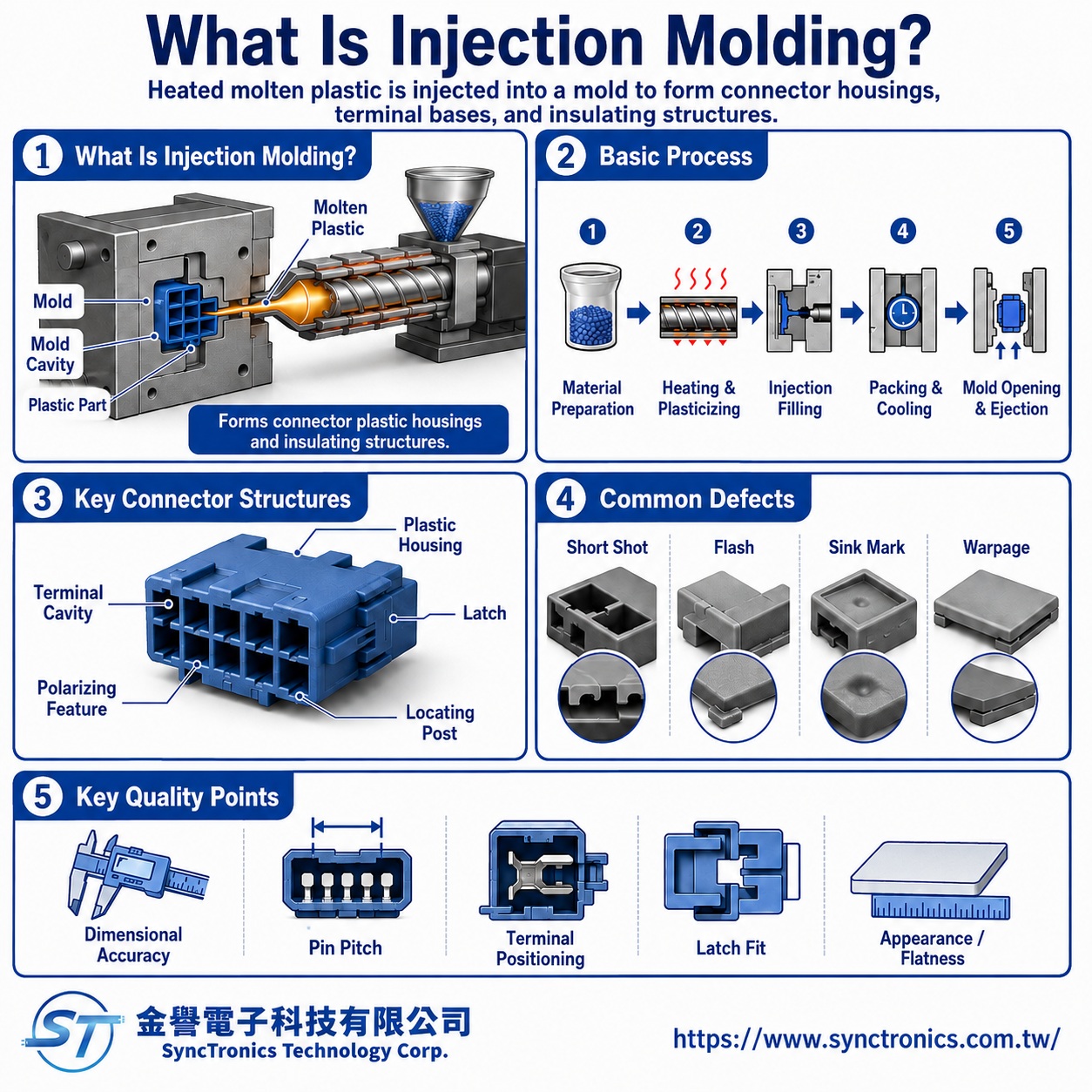
What Is the Basic Injection Molding Process?
The process can be simplified into several stages:
|
Process Stage |
Main Purpose |
|
Material preparation |
Drying, blending, or conditioning the resin as required |
|
Plasticizing |
Heating the resin until it reaches the required flow condition |
|
Filling |
Injecting molten plastic into the mold cavity |
|
Packing / holding |
Compensating for shrinkage and helping stabilize dimensions |
|
Cooling |
Allowing the molded part to solidify in the cavity |
|
Mold opening and ejection |
Removing the finished part from the mold |
Actual molding parameters depend on the resin grade, part geometry, mold construction, and molding machine.
There is no universal injection temperature, pressure, or cooling time that applies to every connector housing.
Which Connector Parts Are Commonly Injection Molded?
Injection molding is mainly used for plastic insulating and structural components.
|
Connector Feature |
Main Function |
|
Housing |
Holds terminals and provides electrical insulation |
|
Terminal cavities |
Controls terminal position and spacing |
|
Latch |
Helps retain the mated connector |
|
Keying feature |
Prevents incorrect orientation or mismating |
|
Guide / locating feature |
Helps align mating parts or PCB placement |
|
Sealing-related structure |
Works with seals or other components in protected designs |
A connector housing is therefore not merely a cosmetic plastic shell.
Many of the connector’s mechanical and insulating functions are built directly into the molded structure.
Why Is Dimensional Accuracy So Important for Connector Molding?
Connectors contain multiple dimensions that must work together.
A typical relationship is:
Terminal → Plastic Housing → Mating Connector → PCB
If a critical dimension is out of tolerance, it may affect assembly or mating performance.
|
Critical Dimension |
Possible Impact |
|
Terminal cavity size |
Terminal may be too loose, too tight, or impossible to insert |
|
Pin spacing |
Mating connector or PCB may not align correctly |
|
Latch geometry |
Retention may be too weak or the connector may not latch |
|
Housing width / height |
Mechanical interference may occur |
|
Guide or keying features |
Mating may become difficult or misaligned |
|
Coplanarity |
PCB mounting and soldering may be affected |
Dimensional stability is therefore one of the most important quality considerations in connector housing molding.
What Plastics Are Commonly Used for Connector Housings?
Different engineering plastics are selected according to temperature, mechanical strength, dimensional stability, flame requirements, and cost.
|
Common Material |
Typical Selection Direction |
|
PBT |
Good balance of electrical insulation, dimensional stability, and cost |
|
LCP |
High flow, thin-wall molding, precision, and elevated-temperature applications |
|
PA66 |
Mechanical strength and toughness |
|
PPS |
High-temperature, chemical resistance, and dimensional stability |
The material name alone does not define final performance.
Two PBT or LCP materials may have different glass-fiber content, flame-retardant systems, shrinkage behavior, flow characteristics, and processing windows.
The exact resin grade should therefore be confirmed.
Why Do Some Engineering Plastics Need Drying Before Molding?
Some engineering plastics absorb moisture.
If the moisture content exceeds the resin supplier’s processing requirement, exposure to high molding temperatures may affect both surface quality and material performance.
Possible problems include:
- Surface streaks
- Bubbles or splay
- Reduced material properties
- Dimensional instability
- Inconsistent molding quality
Drying requirements vary significantly by resin.
The correct drying temperature, time, and target moisture content should follow the recommendations for the exact material grade.
What Factors Affect Injection Molding Quality?
Molding quality is typically influenced by the interaction among material, mold, and processing conditions.
|
Main Factor |
Possible Influence |
|
Resin type |
Flow, shrinkage, strength, and temperature performance |
|
Moisture content |
Surface appearance and material properties |
|
Mold temperature |
Surface quality, crystallization, and dimensions |
|
Melt temperature |
Flow behavior and risk of material degradation |
|
Injection speed |
Filling pattern and weld-line location |
|
Injection / holding pressure |
Filling completeness, shrinkage, and dimensions |
|
Cooling conditions |
Shrinkage, warpage, and process stability |
|
Mold design |
Runner, venting, gate location, and dimensional accuracy |
Even when the same plastic is used, different mold designs or process conditions can produce very different results.
What Are Common Injection Molding Defects in Connector Housings?
|
Common Defect |
Typical Appearance or Effect |
|
Short shot |
Incomplete filling; latch or thin-wall features may be missing |
|
Flash |
Excess plastic appears at parting lines or openings |
|
Sink mark |
Local surface depression or dimensional change |
|
Warpage |
Part bends or loses flatness after cooling |
|
Weld line |
Visible or structurally weaker area where flow fronts meet |
|
Burn mark |
Local discoloration caused by trapped gas, excessive heat, or filling conditions |
Some defects may be cosmetic only.
However, when they occur around terminal cavities, latches, guide features, or mating interfaces, they can directly affect connector function.
Why Is Flash Especially Critical in Connectors?
A small amount of flash on a general plastic cover may only be a cosmetic issue.
On a precision connector, however, flash may appear in:
- Terminal cavities
- Latch areas
- Mating surfaces
- Keying slots
- PCB locating features
This can lead to:
- Difficult terminal insertion
- Increased mating force
- Improper latch operation
- Misalignment
- Assembly failure
Connector inspection must therefore consider whether the defect affects a functional dimension, not simply whether the part looks acceptable.
What Problems Can Warpage Cause?
Plastic shrinks as it cools.
If shrinkage is not uniform throughout the molded part, the housing may warp.
For connectors, warpage can cause:
- Poor PCB coplanarity
- SMT soldering problems
- Pin-position deviation
- Mating difficulty
- Misaligned latch or locating features
Fine-pitch, high-pin-count, or elongated connectors are especially sensitive to dimensional stability and flatness.
Why Can Glass Fiber Affect Shrinkage and Warpage?
Many connector engineering plastics contain glass fiber to improve strength, stiffness, or thermal performance.
During molding, glass fibers tend to align with the resin flow.
This can produce different shrinkage behavior in different directions and influence:
- Dimensional shrinkage
- Warpage
- Directional mechanical strength
- Final part geometry
Gate location, resin-flow direction, and part geometry therefore become important.
For precision connectors, mold design must account for both the external shape and the material’s actual flow and shrinkage behavior.
Why Is Mold Design So Important?
The mold determines much of the final geometry and repeatability of the molded housing.
Connector molds may need to accurately form:
- Terminal cavities
- Latches
- Keying slots
- Thin walls
- Small ribs
- Locating posts
- Parting lines
- Gates and vents
If the mold design itself is fundamentally unsuitable, simply adjusting molding parameters may not fully solve the problem.
Connector molding should therefore be treated as a complete system:
Material + Product Design + Mold + Process Conditions
What Is the Difference Between Injection Molding and Overmolding?
Standard injection molding forms a plastic component directly inside the mold cavity.
Overmolding places an existing component—such as a metal part, cable, or other insert—into the mold before additional plastic is molded around it.
Overmolding may be used for:
|
Application |
Purpose |
|
Cable-to-connector molding |
Integrates the cable and connector body |
|
Strain relief |
Reduces stress at the cable exit |
|
Waterproof structures |
Adds sealing around cable or components |
|
Insert-molded contacts |
Integrates metal components with plastic |
Both use injection molding principles, but mold design, material compatibility, and process control are different.
Can Injection Molding Quality Affect Electrical Performance?
Yes, although the effect is often indirect through mechanical geometry.
For example:
Incorrect terminal cavity position → Terminal misalignment → Contact position changes → Contact force becomes abnormal → Contact resistance or mating reliability may be affected
The housing material itself must also provide appropriate:
- Electrical insulation
- Temperature resistance
- Flame performance
- Dielectric capability
- Dimensional stability
Although the housing is not the primary conductive component, it still plays an important role in the connector’s electrical and mechanical reliability.
How Is Connector Injection Molding Quality Evaluated?
Inspection can be grouped into four main areas:
|
Inspection Area |
Main Checks |
|
Appearance |
Short shots, flash, burn marks, sink marks, cracks |
|
Dimensions |
Pin spacing, cavity position, outline, flatness, tolerances |
|
Assembly |
Terminal insertion, latch, keying, locating features |
|
Function |
Mating, retention, PCB fit, and actual installation |
During NPI or new-mold validation, first-article dimensional inspection, material verification, and assembly trials are often useful for confirming that the mold and product design meet project requirements.
Common Misunderstandings About Injection Molding
|
Common Assumption |
Correct Understanding |
|
Injection molding only creates the plastic appearance |
Many connector positioning, locking, and insulation functions are molded directly into the housing |
|
Any PBT material can be substituted for another PBT |
Different resin grades can have very different flow, shrinkage, and performance |
|
Higher injection pressure always improves molding |
Process parameters must be balanced; excessive pressure can also create defects |
|
Flash is only a cosmetic problem |
Flash in terminal cavities or mating areas can directly affect function |
|
Dimensional problems can always be fixed by machine adjustment |
The root cause may also involve mold, material, or product design |
|
The housing is nonconductive, so it does not affect connector performance |
Housing geometry controls terminal position, insulation, and mating behavior |
Summary
Injection molding is a critical process for producing connector housings and insulating structures.
The goal is not simply to create a plastic shape, but to maintain stable dimensions, terminal positioning, locking features, keying, and mating accuracy across production.
Molding quality is influenced by material selection, moisture control, mold design, filling conditions, packing, and cooling. Defects such as short shots, flash, sink marks, and warpage can become functional failures when they occur in critical connector areas.
For this reason, connector injection molding should be evaluated as a complete system involving material selection, product geometry, mold design, process control, and assembly validation, rather than judging quality by appearance alone.
SyncTronics Solutions
SyncTronics Technology can support connector and electronic interconnect projects by assisting with the evaluation of housing materials, dimensional requirements, temperature performance, flame requirements, mechanical features, and related connector specifications based on PCB mounting, terminal fit, operating environment, and reliability requirements.
For NPI, OEM/ODM, and customized electronic interconnect projects, SyncTronics can also support specification review involving connector housings, terminals, materials, and assembly requirements, together with supply chain integration and coordination with qualified manufacturing partners. Actual material grades and molding conditions should be confirmed against product drawings, resin specifications, and project-specific technical requirements.
Need Wire Harnesses, Connectors, Electromechanical Components, or Custom Solutions? Contact Us Today
Whether you are looking for connectors, cables, wire harness assemblies, electromechanical components, or complete electronic interconnect solutions, SyncTronics provides professional technical support and engineering evaluation for product selection, specification verification, New Product Introduction (NPI), OEM/ODM customization, as well as high-speed transmission, high-reliability, and other specialized application requirements.
We welcome you to visit our Contact Us page and share your project requirements and contact information. Our team is committed to responding quickly and professionally, evaluating the most suitable products and electronic interconnect solutions based on your product specifications, application requirements, and project objectives. We also provide technical recommendations and customized engineering support to help shorten product selection and development time, reduce project risks, and accelerate your path to mass production. We look forward to the opportunity to work with you and provide reliable technical support and practical solutions for every stage of your project.
Related Articles
What Is Manufacturing Technology? Electronics Process & Cable Assembly Guide | SyncTronics Technology
Common Connector Materials Explained | LCP, PBT, ABS, Nylon 6T Applications Guide | SyncTronics Technology
What Is Metal Surface Treatment? Complete Guide | SyncTronics Technology
Disclaimer and Technical Exchange Statement
This content is compiled based on publicly available information and industry experience, intended solely for reference during technical exchanges. It does not constitute any commercial, technical, or legal advice or basis.
The specifications, materials, manufacturing processes, application methods, and related information described herein may vary due to differing design conditions, environmental factors, or usage scenarios. No guarantees are made regarding the completeness, correctness, or suitability of such content.
Readers should verify the suitability with the responsible design or technical personnel based on actual application scenarios, and independently assess all associated risks.
Frequently Asked Questions (FAQ)
- What is Connector Knowledge
- Wire Related issues
- Materials-Related
- Regulatory Issues
- Electronic issues
- Manufacturing Technology
- PM, RD, ME, PE, and QE in Electronics
- What Is NPI?
- What Is Injection Molding? Connector Housing Process and Quality Explained
- Drone Wire Harness Processing: Crimping, Vibration & Flex Design
- What Is Heat Shrink Tubing?
- What Is Crimping? How Crimp Quality Affects Electrical Performance and Reliability
- Crimping vs. Soldering: What's the Difference and Which Is Better?
- What Is SMT (Surface Mount Technology)? How Has It Transformed Electronics Manufacturing?
- What Is Automation in Wire Harness Processing? Benefits and Manufacturing Overview
- What Is Crimp Height? Why Is It Important in Terminal Crimping?
- What Is Wire Harness Assembly? A Complete Guide to the Wire Harness Manufacturing Process
- SMT vs. Through-Hole (DIP): What's the Difference and When Should Each Be Used?
- Testing & Verification
- Quality Management
- History & Evolution