
Why Do Drone Connectors Become Loose? Vibration Resistance, Polarization and Retention Design
Why Do Drone Connectors Become Loose? Vibration Resistance, Polarization and Retention Design
During high-speed motor operation, takeoff, landing and rapid attitude changes, drones are continuously exposed to vibration, mechanical shock and acceleration. Connectors and wire harnesses linking flight controllers, GPS modules, power modules, sensors and electronic speed controllers are subjected to the same mechanical loads.
When a drone experiences a “loose connector,” the problem does not always mean that the plug and receptacle have physically separated. It may also involve terminal back-out, contact micro-movement, stress at the crimp area, repeated cable pulling or an incompletely mated connector.
For flight systems, even a very brief interruption may cause GPS signal loss, sensor errors, flight controller resets or temporary power loss. Vibration resistance, locking mechanisms and proper wire harness retention are therefore critical to connector reliability.
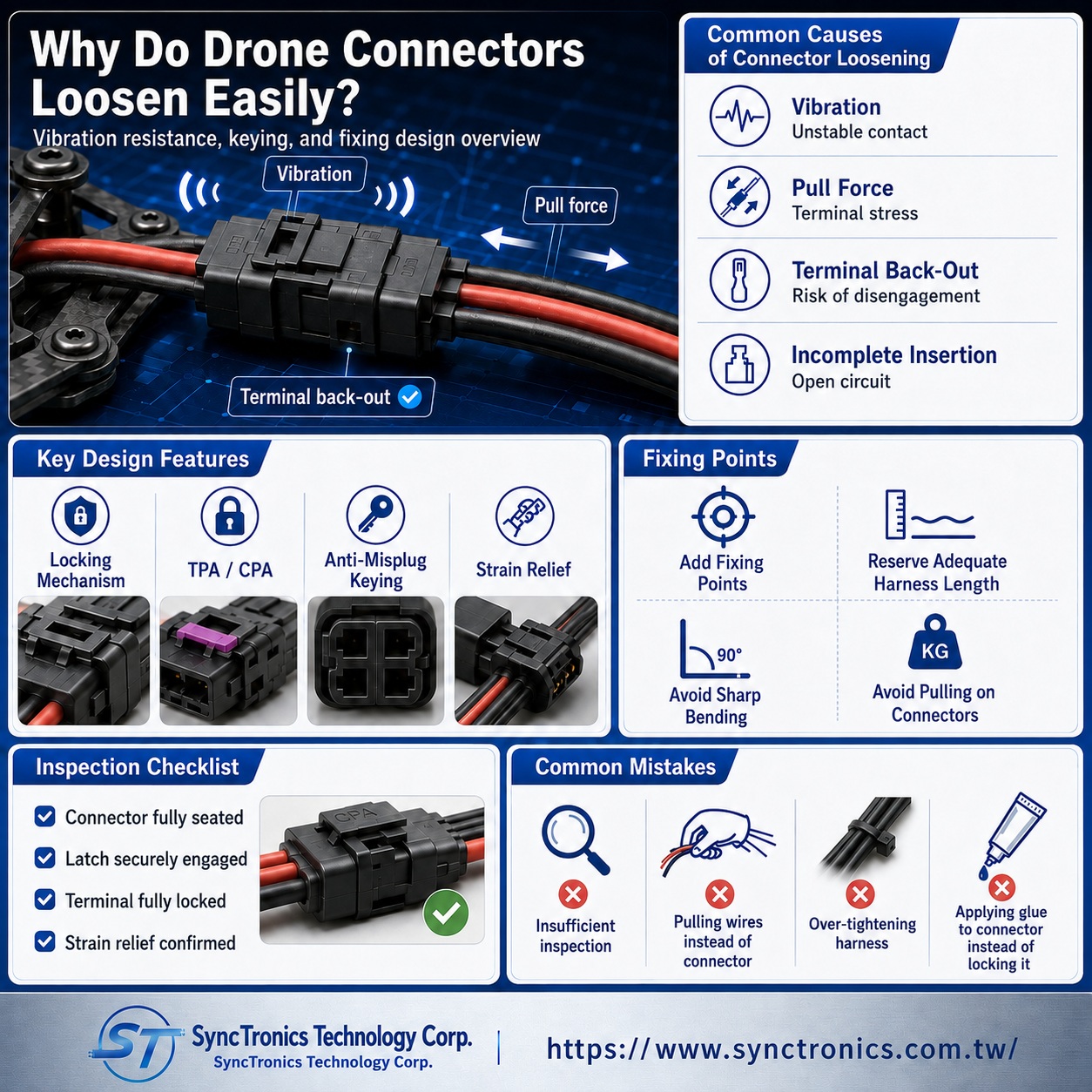
What Commonly Causes Drone Connectors to Become Loose?
|
Cause |
Possible Problem |
Improvement Direction |
|
Motor and propeller vibration |
Connector gradually backs out or contact becomes unstable |
Use positive-lock or secondary-lock designs |
|
Cable pulling |
Mechanical load acts directly on terminals |
Add retention and strain relief |
|
Terminal not fully seated |
Terminal back-out |
Verify terminal locking and secondary locks |
|
Connector not fully mated |
Intermittent electrical contact |
Use clear locking and mating confirmation |
|
Insufficient connector retention |
Weak holding force |
Select a series suitable for vibration environments |
|
Cable too heavy or too stiff |
Continuous bending load on connector |
Adjust wire gauge, flexibility and routing |
|
Incorrect mating orientation |
Forced insertion or terminal damage |
Use mechanical polarization and keying |
|
Poor harness retention |
Cable movement, abrasion and resonance |
Add suitable fixing points and controlled slack |
Why Are Connectors With Latches Better for Drones?
A basic connector may rely mainly on friction between the contacts and housing to remain mated. In low-vibration environments, this may be sufficient. Under continuous vibration, however, friction alone may not provide enough retention.
Connectors with positive locks, latch locks or other secure mechanical locking features use a physical latch to keep the plug and receptacle engaged after mating, reducing the risk of accidental separation.
Connector retention systems may range from simple friction retention to positive locks, connector position assurance devices and screw locking. As vibration severity increases, stronger mechanical retention becomes more important.
For drones, interfaces such as GPS, flight control, CAN, telemetry and critical sensors should therefore be evaluated not only by pitch, pin count and size, but also by their locking structure.
If the Connector Is Locked, Why Can the Terminal Still Become Loose?
This is a common issue in drone wire harnesses.
Connector reliability actually involves two different levels:
Connector mating retention: keeps the plug and receptacle from separating.
Terminal retention: keeps each metal terminal correctly positioned inside the housing.
Even when the outer connector latch remains locked, a terminal may still move backward if it was not fully seated, the terminal locking lance was damaged, the housing was deformed or the cable was subjected to continuous pulling.
Terminal back-out can lead to incomplete contact engagement and intermittent electrical failures.
For this reason, harness inspection should not stop at confirming that “the connector is plugged in.” Each terminal must also be properly seated and retained.
What Are TPA and CPA?
High-reliability connector systems often use TPA and CPA features.
TPA (Terminal Position Assurance) is used to confirm or reinforce correct terminal installation inside the housing and help reduce the risk of incomplete seating or terminal back-out.
CPA (Connector Position Assurance) is used after the plug and receptacle are fully mated to secure the primary connector latch and reduce the risk of accidental unlatching.
Some high-vibration applications use both mechanisms to provide two levels of mechanical protection.
Not every drone requires a large automotive-style connector with TPA or CPA, but the design principle is important:
The more critical the interface, the higher the vibration level and the more serious the consequence of failure, the stronger the required retention strategy should be.
Is Polarization Only Used to Prevent Reverse Insertion?
Polarization, keying or mechanical coding is used to prevent an incorrect orientation, wrong mating pair or incompatible connector from being inserted.
This is especially important in drones because flight controller boards may contain multiple connectors of similar size for GPS, CAN, telemetry, I²C and other interfaces.
If several interfaces use the same pin count and similar housings, relying only on wire color or visual recognition may result in incorrect connections during assembly, maintenance or module replacement.
Mechanical keying may use housing geometry, ribs, slots, positioning keys or different coding features to restrict incorrect mating.
However, polarization does not replace pin-definition verification. Even if two connectors can physically mate, power, ground, TX, RX, CAN High and CAN Low assignments must still be confirmed.
Why Does Wire Harness Retention Affect Connector Loosening?
If the harness is not properly secured, the entire cable weight and flight vibration can be transferred directly to the connector.
This is especially significant for thicker power wires, long GPS harnesses or cables routed between different structural sections of the aircraft.
Appropriate strain relief should therefore be provided near the connector.
Depending on the design, this may include:
- Cable ties
- Mounting clips
- Cable clamps
- Braided sleeving
- Heat-shrink tubing
- Backshells
- Harness routing channels
- Controlled cable slack
The purpose of retention is not to pull the cable as tightly as possible. Instead, the structure should carry the cable weight and vibration so that the terminal and connector do not absorb the full mechanical load.
The cable should also not make an immediate sharp bend at the connector exit because this can concentrate stress at the crimp, solder joint or terminal root.
Does a Shorter Wire Always Reduce the Risk of Loosening?
Not necessarily.
An excessively long wire may swing, rub against surrounding structures and add unnecessary weight. However, a wire that is too short can place constant tension on the connector because of assembly tolerance, frame movement or vibration.
A better approach is to provide appropriate and controlled slack and add a suitable fixing point near the connector.
The cable should be able to bend naturally without large uncontrolled movement.
Modules that require regular maintenance or removal should also have enough service length so that technicians do not need to pull directly on the wire during disassembly.
Can You Pull the Wire to Disconnect a Connector?
It is not recommended.
The correct method is to grip the connector housing, release the latch and then separate the connector.
Pulling directly on the wire transfers force to the crimp and terminal and may eventually cause:
- Broken conductor strands
- Loose crimp connections
- Terminal back-out
- Housing latch damage
- Increased contact resistance
Small flight controller and GPS connectors are particularly vulnerable to damage from improper removal because of their compact terminals and wire sizes.
Should All Drone Connectors Be Glued in Place?
Using adhesive should not be treated as the universal solution for connector loosening.
Some applications may use adhesive, potting compounds, silicone or other materials for additional retention or environmental protection. However, suitability depends on factors such as:
- Future maintenance requirements
- Material compatibility with the connector housing
- Whether the adhesive interferes with the latch
- Risk of material entering the contact area
- Operating temperature
- Vibration and thermal expansion
- Rework and disassembly requirements
If the connector selection, terminal retention or harness support is fundamentally inadequate, simply gluing the connector in place may only hide the original problem.
A better sequence is to verify the connector, latch, terminal and harness-retention design first, then evaluate additional adhesive or potting only when the application requires it.
How Can You Check Whether a Drone Harness Is Likely to Become Loose?
During prototype or NPI stages, the following checks are useful:
- Confirm that the plug and receptacle are fully mated
- Confirm that the latch is fully engaged
- Verify that every terminal is completely seated
- Apply a light pull to each wire to confirm that the terminal does not back out
- Verify TPA or secondary-lock engagement where applicable
- Check for concentrated stress at cable exits
- Confirm that suitable harness fixing points are provided
- Check whether power and signal wires contact moving structures
- Verify electrical stability while motors are operating
- Reinspect connectors and terminals after vibration or flight testing
For applications with higher safety or reliability requirements, vibration, shock, pull-force, mating-cycle and electrical test conditions should be established according to the actual operating environment.
Connector reliability should not be judged only by whether a connector “feels tight.”
Common Design Mistakes
Judging reliability only by how tight the connector feels
Mating force alone does not represent vibration resistance. Latches, terminal retention, harness weight and cable support must also be considered.
Assuming a latch prevents every type of failure
A latch only addresses part of the connector mating problem. Individual terminals may still back out.
Securing the harness too tightly
Excessive restraint may transfer vibration and stress directly into the connector and can create fatigue near fixing points.
Using identical housings without sufficient keying
This increases the risk of incorrect mating during assembly or maintenance and may cause reverse polarity or module damage.
Applying glue whenever a connector becomes loose
If the root cause is poor terminal seating, crimping or harness design, adhesive does not solve the underlying reliability issue.
Conclusion
Drone connector loosening is not a single-component problem. It results from the combined effects of connector locking, terminal retention, cable weight, vibration, installation method and maintenance practices.
For critical GPS, flight control, power, CAN and sensor interfaces, connectors with positive mechanical locking should be prioritized, and all terminals should be verified for complete seating.
Applications with higher reliability requirements may also benefit from TPA, CPA or other secondary-lock mechanisms.
At the same time, wire harnesses should include proper retention, controlled slack and strain relief so that the connector does not carry the full weight and vibration of the cable.
A reliable drone interconnect design is not simply about “choosing a connector that will not fall out.” It requires evaluation of the connector, terminal, wire, harness assembly, retention method and complete vibration environment as one system.
SyncTronics Solutions
SyncTronics Technology provides integrated support for drone connectors, flight controller harnesses, GPS harnesses, power cables, signal wires and customized electronic interconnect solutions.
Based on equipment interfaces, pin count, wire gauge, vibration environment, locking method, terminal retention and harness-fixing requirements, we can assist customers with specification verification and suitable connector and harness configurations.
For high-vibration equipment, New Product Introduction (NPI), special wiring sequences, interface conversion and OEM/ODM projects, SyncTronics can support the evaluation of connectors and harnesses with suitable locking, polarization, secondary-lock and strain-relief structures to help reduce risks associated with connector loosening, terminal back-out, intermittent disconnection and incorrect mating.
Need Wire Harnesses, Connectors, Electromechanical Components, or Custom Solutions? Contact Us Today
Whether you are looking for connectors, cables, wire harness assemblies, electromechanical components, or complete electronic interconnect solutions, SyncTronics provides professional technical support and engineering evaluation for product selection, specification verification, New Product Introduction (NPI), OEM/ODM customization, as well as high-speed transmission, high-reliability, and other specialized application requirements.
We welcome you to visit our Contact Us page and share your project requirements and contact information. Our team is committed to responding quickly and professionally, evaluating the most suitable products and electronic interconnect solutions based on your product specifications, application requirements, and project objectives. We also provide technical recommendations and customized engineering support to help shorten product selection and development time, reduce project risks, and accelerate your path to mass production. We look forward to the opportunity to work with you and provide reliable technical support and practical solutions for every stage of your project.
Related Articles
How to Select Drone Connectors and Wire Harnesses | SyncTronics Technology
Drone Connectors: XT30, XT60, JST-GH and DF13 | SyncTronics Technology
How to Select Drone Battery Connectors: XT30, XT60 and XT90 | SyncTronics Technology
What Is Connector Pin Count? Complete Guide | SyncTronics Technology
Disclaimer and Technical Exchange Statement
This content is compiled based on publicly available information and industry experience, intended solely for reference during technical exchanges. It does not constitute any commercial, technical, or legal advice or basis.
The specifications, materials, manufacturing processes, application methods, and related information described herein may vary due to differing design conditions, environmental factors, or usage scenarios. No guarantees are made regarding the completeness, correctness, or suitability of such content.
Readers should verify the suitability with the responsible design or technical personnel based on actual application scenarios, and independently assess all associated risks.
Frequently Asked Questions (FAQ)
- What is Connector Knowledge
- What Is a Connector?
- Euro-Style vs. Barrier Terminal Blocks
- Ring vs. Fork Terminals: Differences
- What Is an IDC Connector?
- Box Header vs. Ejector Header: Latching, Ejection, and When to Use Each
- What Is a Box Header?
- 6 Common Connector Selection Mistakes and How to Avoid Them
- How to Select a USB Type-C Connector: Mating Cycles, Current Rating & PCB Mounting
- How to Select Industrial Automation Connectors: Locking, Vibration Resistance & Retention
- How to Select Energy Storage Connectors: Current Rating, Contact Resistance & Keying
- Why Do High-Current Connectors Overheat? Contact Resistance, Terminals & Crimp Quality
- What Is a Terminal Block? Types, Structure & Selection
- Wire-to-Board vs. Board-to-Board Connectors: Structure and Selection
- How to Select Drone Connectors and Wire Harnesses: Power, Flight Controller, GPS and Signal Connections
- What Connectors Are Commonly Used in Drones? XT30, XT60, JST-GH, and DF13 Explained
- How to Select Drone Battery Connectors: XT30, XT60 and XT90
- Why Do Drone Connectors Become Loose? Vibration Resistance, Polarization and Retention Design
- RJ45 Connector Structure and Applications Guide
- What Is Connector Pitch?
- What Does Connector Pin Count Mean?
- What Is the Difference Between a Terminal, a Connector, and a Coupling?
- What Is Contact Resistance, and What Does It Affect?
- What Is Connector Insertion and Withdrawal Force?
- What Is Retention Force?
- What Is Poka-Yoke (Error-Proofing) Design?
- What Is Gold Plating Thickness? Why Does It Affect Connector Lifespan?
- What Is the Difference Between SMT Connectors and DIP Connectors?
- Wire Related issues
- Materials-Related
- Regulatory Issues
- Electronic issues
- Manufacturing Technology
- Testing & Verification
- Quality Management
- History & Evolution